Adjustable damping energy storage type tuned mass damper

A technology of tuning mass damping and adjusting damping, which is applied to building components, shockproof, etc., can solve problems affecting system stability, difficult adjustment of damping ratio, and affecting service life, etc., and achieves simple structure, low maintenance cost, and good reliability Effect

Active Publication Date: 2012-06-13
中铁桥研科技有限公司 +2
View PDF10 Cites 38 Cited by
  • Summary
  • Abstract
  • Description
  • Claims
  • Application Information

AI Technical Summary

Problems solved by technology

In order to make the tuned mass damper have better vibration reduction performance and make the damping parameters more stable and adjustable, there are many methods in the prior art to maximize the vibration control effect by adjusting the frequency and damping ratio of the tuned mass damper. , for example, the patent number is 200810237452.6, the authorization number is CN101492941A, and the invention named "a liquid mass double-tuning vibration reduction method" uses fluid-solid coupling vibration to completely separate the mass parameters, stiffness parameters and damping parameters, and the tuning is convenient. However, using The size of the oil hole adjusts the damping force, and the damping ratio of the system is adjusted by using an open damping hole. For dampers with small modal masses, better results can be achieved, while for large modal masses, damping The force becomes larger accordingly, and the adjustment of the damping ratio has certain difficulties; the patent number is 200810082654.8, the authorization number is CN 101457553A, and the invention named "tunable mass damper with adjustable spring stiffness" uses a spring stiffness adjustment device to adjust the shock absorber Rigidity simplifies the difficulty of adjustment work, but when adjusting the damping of the shock absorber, the oil damper is used, and there is a problem of oil leakage in the seal; the patent number is 02145115. Invention of the tuned mass damper by increasing or decreasing the number

Method used


Image

  • Adjustable damping energy storage type tuned mass damper
  • Adjustable damping energy storage type tuned mass damper
  • Adjustable damping energy storage type tuned mass damper

Examples


Embodiment Construction

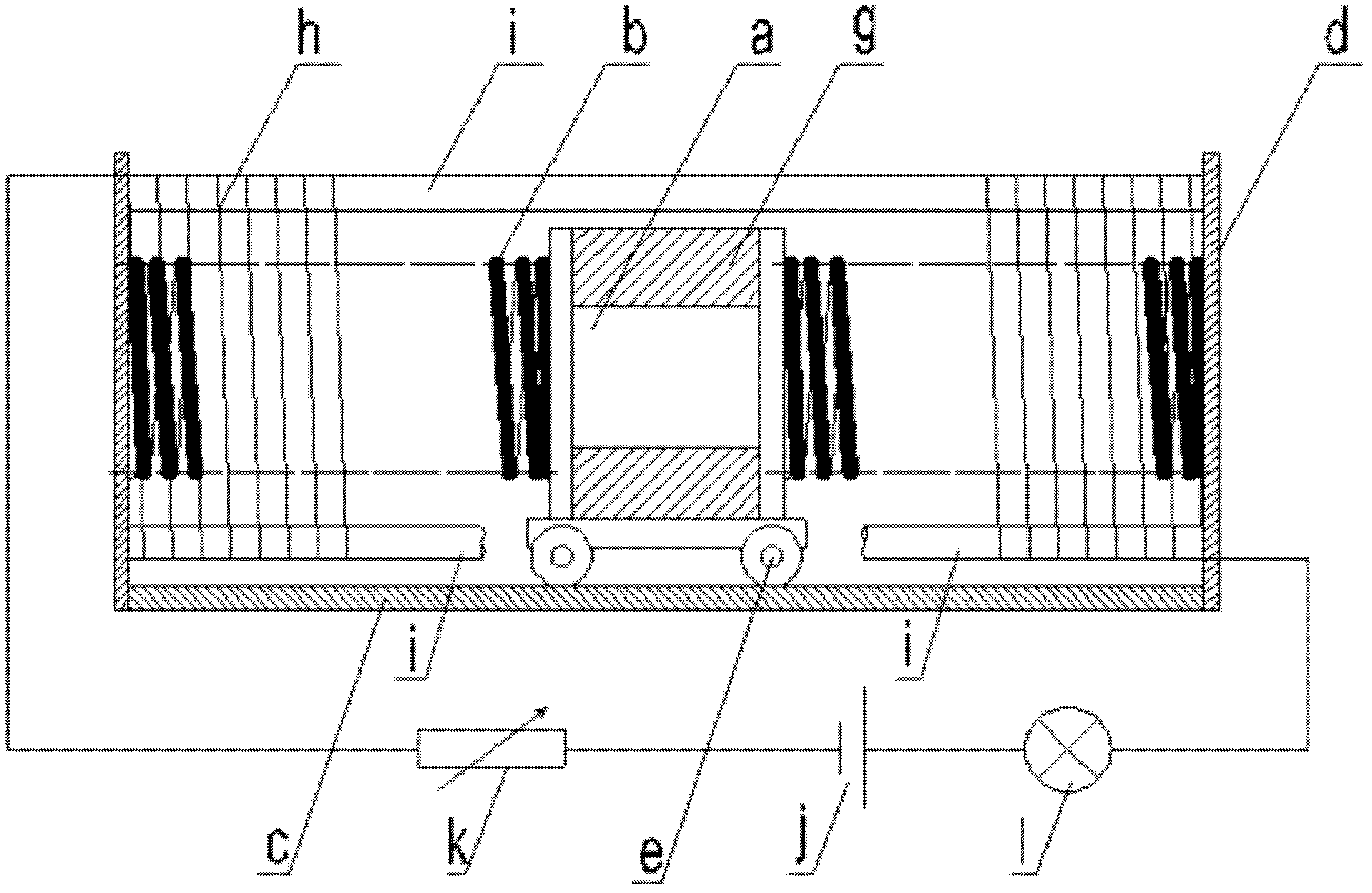
[0022] The present invention will be further described below in conjunction with the accompanying drawings and embodiments. figure 1 It is a structural schematic diagram of the adjustable damping energy storage tuned mass damper of the present invention. The embodiment is a pedestrian bridge, the first-order lateral vibration modal mass is 100 tons, and the lateral vibration frequency is 1.2 Hz. The vibration control of the bridge is carried out by adopting the scheme of multiple tuned mass dampers. At the position of the maximum modal vibration displacement of the bridge Eight tuned mass dampers are set, and the ratio of the modal mass of each tuned mass damper to the modal mass of the first-order lateral vibration of the bridge is 0.6%. In the present embodiment, the inertial mass a, permanent magnet g and rolling bearing e constitute a total of 600kg; the stiffness of a single cylindrical helical spring b is 16.2kN / m, the diameter of its spring steel wire is 12mm, and the m...


PUM


Abstract

The invention provides an adjustable damping energy storage type tuned mass damper. A damping adjusting device of a damper of consists of a permanent magnet, coils, auxiliary rods, an energy storage battery, an adjustable resistor, a light-emitting diode (LED) pre-warning indicator light; in the reciprocating motion process that the damper absorbs the vibration energy of a main structure so as to generate inertial mass, a cylindrical spiral spring provides damping, the permanent magnet generates a variable magnetic field, induced electromotive force is generated in the coils so as to generate induction current, and the induction current generates electromagnetic damping to inhibit the movement of the permanent magnet; the adjustable resistor in the damping adjusting device is adjusted, so the magnitude of the electromagnetic damping is changed, and the damping ratio of a structure reaches the optimum damping ratio; and residual energy is recovered by using the energy storage battery, the LED pre-warning indicator light provides a pre-warning indication for a pedestrian and a vehicle, and multiple effects of vibration controlling, clean energy recovery, pre-warning and alarming of vibration conditions and the like.

Description

technical field [0001] The invention relates to a vibration damping device for suppressing structural vibration, which is especially suitable for vibration control of construction engineering structures, belongs to the technical field of engineering structure vibration damping, and specifically relates to a non-contact energy consumption, precisely adjustable damping ratio, The energy can be recovered and utilized, and it is a tuned mass damper that can suppress vibration and provide early warning for bridges or high-rise buildings. Background technique [0002] With the continuous development of science and technology, the span of engineering structures is getting larger and higher, and the structure will generate relatively strong vibration under the action of external dynamic loads such as earthquakes or strong winds, which will increase the fatigue and damage of the structure. This leads to the failure of the structure or even catastrophic accidents before the design lif...

Claims


Application Information

Patent Timeline
IPC IPC(8): E04B1/98
Inventor 王波刘鹏飞黄清李武王庆曾朱治宝王翔李东超柴小鹏郭翠翠张波
Owner 中铁桥研科技有限公司
Why Eureka
Try Eureka