
Harmonic optimization technology

a technology of harmonic optimization and optimization technology, applied in the field ofapparatus, to achieve the effect of reducing vibration, preventing undue upset, and reducing vibration transmission

Inactive Publication Date: 2001-05-01
SCHWINKENDORF KEVIN +1
View PDF62 Cites 42 Cited by
  • Summary
  • Abstract
  • Description
  • Claims
  • Application Information

AI Technical Summary

Benefits of technology

A particular load will have some muzzle velocity variation from cartridge to cartridge, so that any variation in the angular deflection of the muzzle in time will result in a statistical variation in dispersion angle. Minimizing the time rate of change of the muzzle deflection, coupled to statistical variation in muzzle velocity, and thus the time of flight of the bullet to the exit point at the muzzle, will minimize group size making the rifle less sensitive to small variations in the bullet travel time. While this will reduce the group size of bullet impact, the point of impact may vary significantly with different loads and bullet weights inasmuch as the objective of the approach was to make the bullet exit the barrel while it was at the point of extreme deflection. This extreme deflection may direct the muzzle at different points of impact for different loads.
A system or apparatus for a rifle barrel, and other devices employing a cantilever portion from which a projectile is launched or fired, developed through a harmonic optimization technology achieves improved bullet accuracy by significantly reducing the magnitude of the barrel muzzle angular dispersion caused by vibrations. Thus, the specific sight-in for different loads will be more predictable, i.e., from exterior ballistics. Deviation of the point of impact from the ideal predictions of exterior ballistics will be minimized. Bullet accuracy will be less sensitive to variations in ammunition loads.
The present invention comprises an improvement to known vibration dampening systems or apparatus by first reducing vibrations at the muzzle by first partially decoupling and isolating the vibrations initiated in the barrel near the cartridge chamber or breach end of the barrel as a result of a launching and the transit of a projectile through the barrel, thereby reducing vibration transmission to the muzzle end of the barrel. The launching may be by, but need not be limited to, chemical, thermodynamic, or electromagnetic processes. Secondly, the vibrations are modified so that the angular dispersion at the muzzle, which gives final direction to the projectile, is minimized. This may be accomplished by a method which comprises tuning the barrel to produce a standing wave, corresponding to the frequency of the short term vibrational response, in response to barrel vibrations that bend the barrel proximal to the muzzle so that the dispersion angle at the muzzle remains nearly parallel with the bore axis. This method allows the projectile to exit the barrel at a point where the standing wave has maximum displacement or zero slope. In the preferred embodiment of the apparatus disclosed, the standing wave is produced by a harmonic oscillator and an inertial mass. However, it will be apparent to those skilled in the art that other hardware configurations will produce such a standing wave in response to the short term vibrational response of the barrel. The appended claims are therefore intended to cover all such configurations as fall within the true spirit and scope of the invention. Thirdly, the pressures of expanding gases on the back of the bullet as it exits the muzzle are reduced in order to prevent undue upset on the bullets' angle of flight and axis of rotation. Moreover, in devices such as rifles comprising a barrel and a rifle stock, said method further comprises the step of adjusting the vibrational boundary conditions between the barrel and the rifle stock. Thus bullet path dispersion is minimized, not just for a particular load, but for any load with variations in bullet weight and powder load. The impact location of a specific bullet weight and powder load will be primarily a vertical relationship to the point of aim which is based on the predictable trajectory of the bullet.

Problems solved by technology

Variations in either powder loads or bullet weights cause changes in muzzle velocities which result in different times between powder ignition and the time when the bullet leaves the muzzle.

Method used


Image

  • Harmonic optimization technology
  • Harmonic optimization technology
  • Harmonic optimization technology

Examples


Embodiment Construction

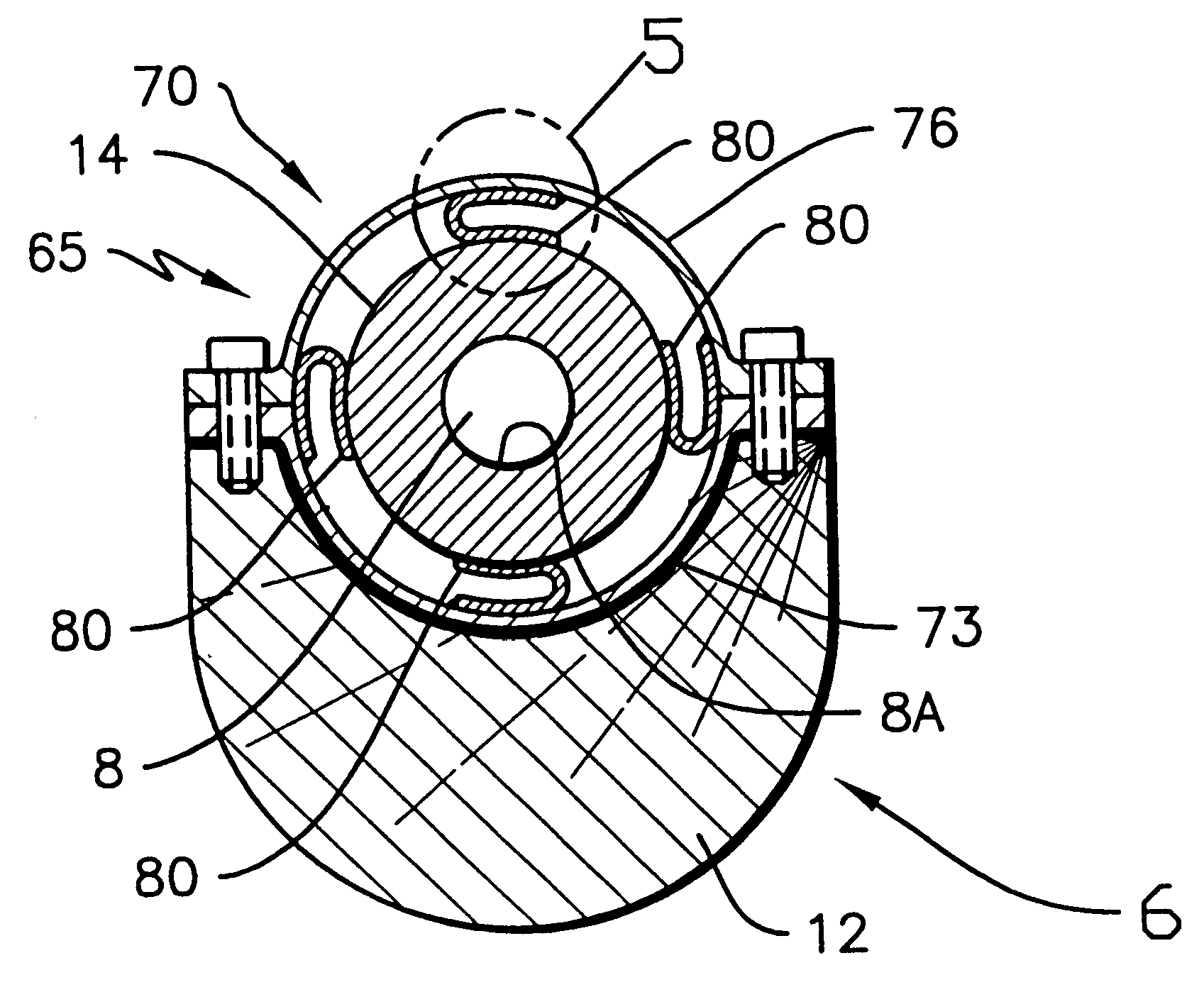
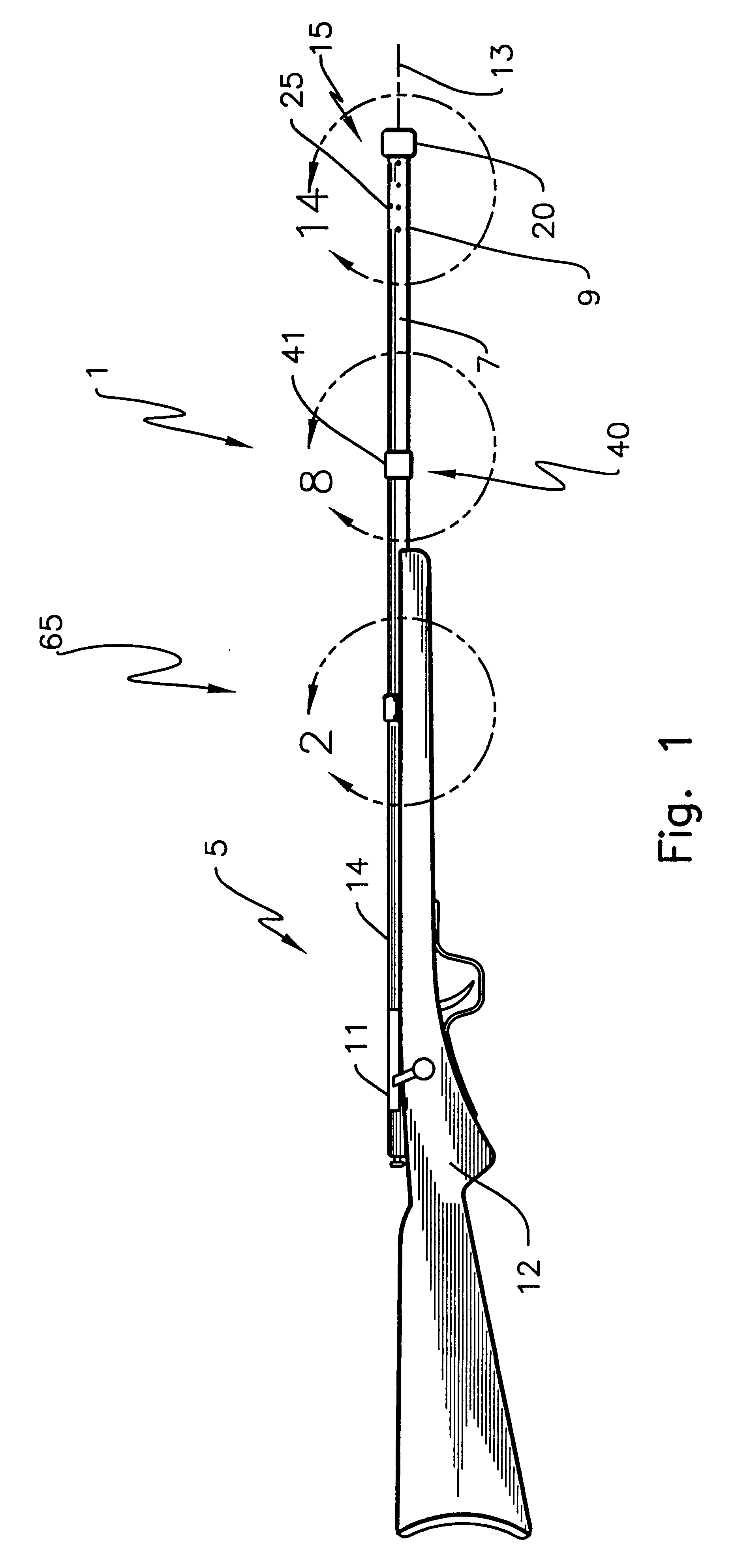
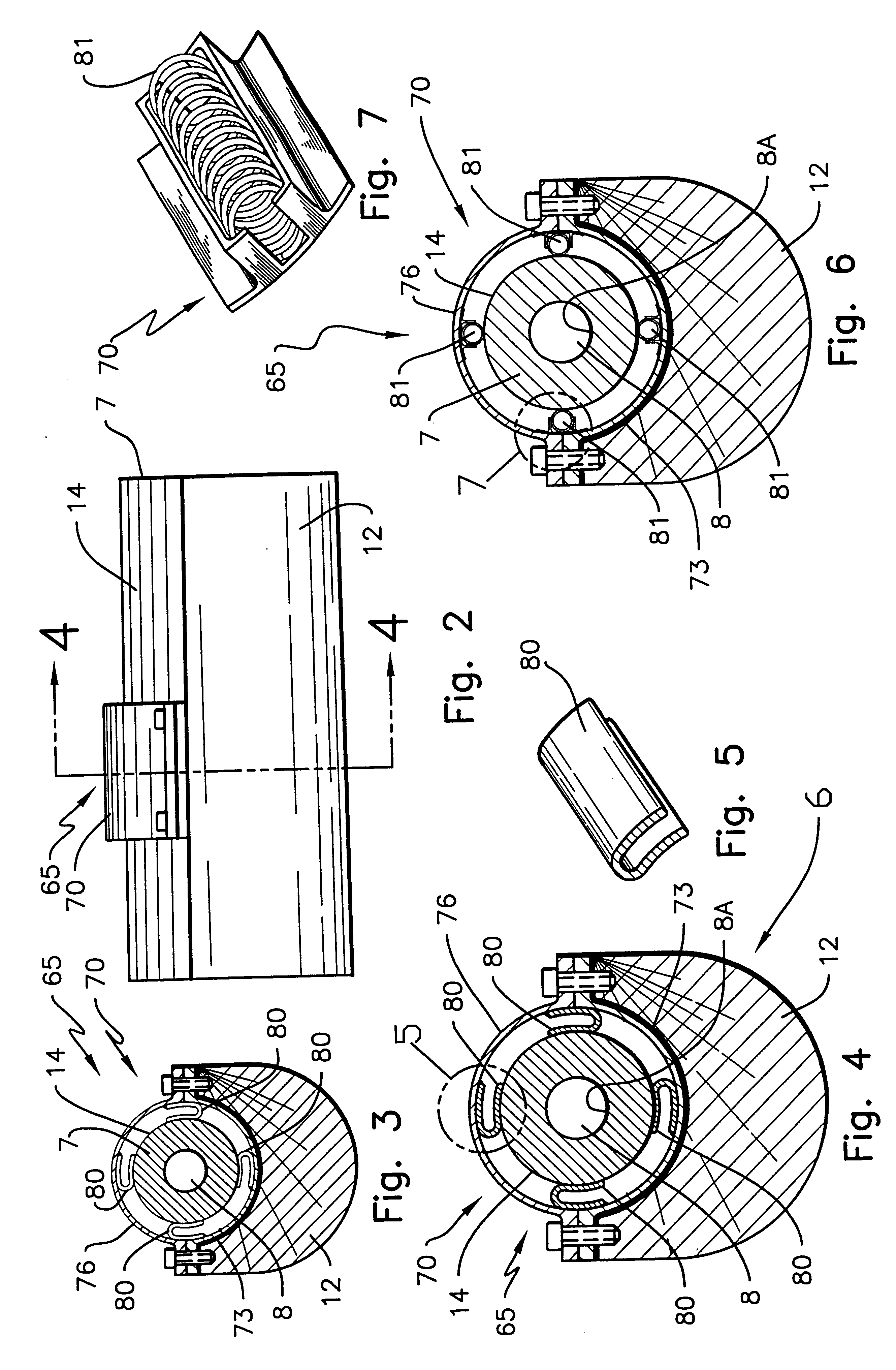
The harmonic optimization technology vibration controlling system 1 disclosed herein is illustrated in FIG. 1 through FIG. 15 as applied to a rifle 5 having a barrel 7, a barrel bore 8, a muzzle 9, a cartridge chamber 11, a bore axis 13, a barrel surface 14 and a bore surface 8A. The cartridge chamber 11 is distal from the muzzle 9. The barrel 7 having a short term vibrational response, to the combustion of a cartridge in the cartridge chamber 11 and to the transit of a bullet through the barrel 7. The muzzle 9 having a dispersion angle relative to the bore axis 13. System components, in the preferred embodiment, include a harmonic oscillator 15, formed at or affixed by means at the barrel muzzle 9, the harmonic oscillator 15 having harmonic oscillator mass 20, wall thickness, material composition, extension length and flexible cylinder discontinuities. The harmonic oscillator 15 composed of a harmonic oscillator mass 20 and a flexible cylinder extension 25 of the muzzle 9. The harm...


PUM


Abstract

A method and an apparatus or apparatus system for vibration control, by harmonic optimization technology, of vibrations in the cantilever or barrel, portion of a device from which a projectile is fired or launched along the centerline of the cantilever. More particularly this invention relates to rifles, where the rifle barrel is a cantilever portion, and methods and apparatus for increasing the accuracy of firing projectiles. The invention is principally directed to a method and apparatus including a mass device affixed to a flexible cylinder extension at the muzzle end, inertial mass devices, having combustion pressure reduction features, affixed intermediate the muzzle end and the cartridge chamber, and a spring suspension system between barrel and rifle stock affixed proximal to the cartridge chamber. This system decreases the angular dispersion of barrel vibrations at the muzzle resulting from the firing of projectiles through such barrels.

Description

FIELD OF THE INVENTIONThe present invention relates generally to apparatus with a cantilever portion from which a projectile is fired or launched along the centerline of the cantilever and in particular to the controlling of vibrations of the cantilever component of such an apparatus. More particularly this invention relates to rifles, where the rifle barrel is a cantilever portion, and methods and apparatus for increasing the accuracy of firing projectiles. The invention is principally directed to a method and apparatus including a mass device affixed to a flexible cylinder extension at the muzzle end, inertial mass devices affixed intermediate the muzzle end and the cartridge chamber, and a spring suspension system affixed proximal to the cartridge chamber. This system decreases the angular dispersion of barrel vibrations at the muzzle resulting from the firing of projectiles through such barrels.BACKGROUND OF THE INVENTIONAccuracy and consistency in striking a target is a princip...

Claims


Application Information

Patent Timeline
Patent Type & Authority Patents(United States)
IPC IPC(8): F41A21/36F41A21/00F41A21/28F41A21/48F41C27/00F41C27/22
CPCF41A21/00F41A21/28F41A21/36F41A21/487F41C27/22
Inventor SCHWINKENDORF, KEVINROBLYER, STEVEN P.
Owner SCHWINKENDORF KEVIN
Learn More