Insulator for audio and method for evaluating same
a technology for insulators and audio, applied in the field of insulators for audio, can solve the problems of inability to reproduce original sound as faithfully as human hearing perceives, and the quality of sound is changed, so as to improve acoustic characteristics, improve sound quality, and improve sound quality
- Summary
- Abstract
- Description
- Claims
- Application Information
AI Technical Summary
Benefits of technology
Problems solved by technology
Method used
Image
Examples
first embodiment
[1-1] Basic Structure of Insulator in Embodiment
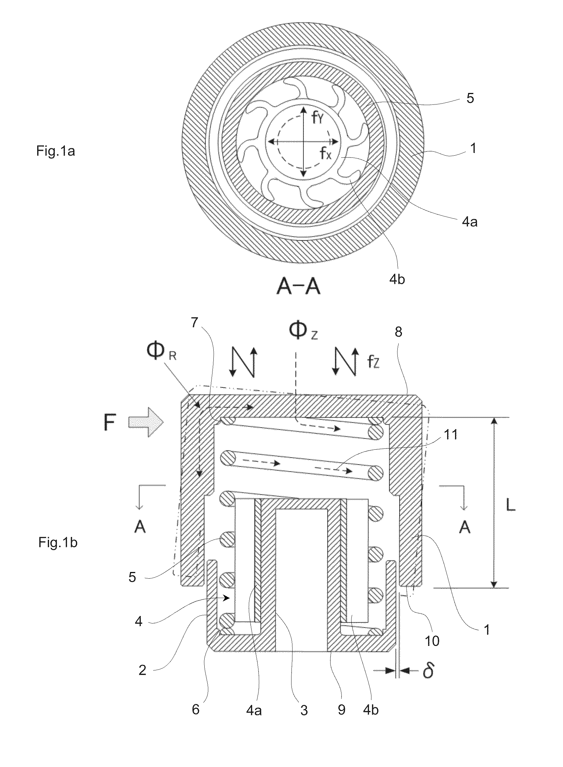
[0109]FIG. 1 illustrates an insulator for audio according to the first embodiment of the present invention, in which FIG. 1a is a top cross-sectional view (A-A cross-sectional view in FIG. 1b), and FIG. 1b is a front cross-sectional view. Reference numeral 1 represents an upper sleeve (upper support member) as a wind-bell member, 2 represents a lower sleeve (lower support member), 3 represents a tubular part that is formed in the central part of the lower sleeve 2 with protruding, and 4 represents a surging prevention member (vibration generation prevention means) that is attached to an outer circumferential part of the tubular part 3. In the present embodiment, the upper sleeve 1 plays both roles as the upper support member and a resonant member (wind-bell member).
[0110]For the upper sleeve 1 and the lower sleeve 2, brass having good properties as an acoustic material (trial part A in Table 4) is used. The surging prevention member 4 ...
second embodiment
[0210]FIG. 26 is a front cross-sectional view of an insulator for audio according to a second embodiment of the present invention, and illustrates the case where a mechanism for finely adjusting a height of the insulator is provided.
[0211]Reference numeral 251 represents an insulator main body part, 252 represents a lower sleeve (lower support member), and 253 represents a lower base part (base part), which is attached to the lower sleeve 252 through a screw part 254. A single body of a speaker having a voice coil and a permanent magnet is typically placed on a front side of the main body, and therefore the position of the center of gravity of the speaker main body is often eccentric toward the front side. In the case of attaching the present insulator, the speaker main body is placed with being tilted although an amount of the tilt is small. In this case, by using the screw part 254 provided between the lower base part 253 and the lower sleeve 252, and correcting the height of the ...
third embodiment
[0212]FIG. 27 is a front cross-sectional view illustrating an insulator for audio according to a third embodiment of the present invention and a method for supporting an audio device. FIG. 28 is a front cross-sectional view illustrating a state where the audio device is supported through a spike placed on the audio device side. Reference numeral 901 represents an upper sleeve (upper support member), 902 represents a lower sleeve (lower support member), 903 represents a tubular part that is formed in the central part of the lower sleeve 902 with protruding, 904 represents a surging prevention member, 905 represents a spring coil, and 906 and 907 represent spring coil aligning parts. Reference numeral 908 represents a spike tip receiving part, which is formed in the central part of the upper sleeve 901. Reference numeral 909 represents a through-hole that is formed in the central part of an upper end of the tubular part 903, and 910 represents a bolt that is fastened to the upper slee...
PUM
 Abstract
Description
Claims
Application Information
 - R&D
- Intellectual Property
- Life Sciences
- Materials
- Tech Scout
- Unparalleled Data Quality
- Higher Quality Content
- 60% Fewer Hallucinations
Browse by: Latest US Patents, China's latest patents, Technical Efficacy Thesaurus, Application Domain, Technology Topic, Popular Technical Reports.
© 2025 PatSnap. All rights reserved.Legal|Privacy policy|Modern Slavery Act Transparency Statement|Sitemap|About US| Contact US: help@patsnap.com


