Tractive effort system and method

Active Publication Date: 2013-08-15
GE GLOBAL SOURCING LLC
View PDF26 Cites 25 Cited by
  • Summary
  • Abstract
  • Description
  • Claims
  • Application Information

AI Technical Summary

Benefits of technology

[0013]In one embodiment, a nozzle is provided for use with a tractive effort system for increasing adhesion. The tractive effort system is for a vehicle having a wheel contacting a surface. The nozzle includes a body defining a passageway therethrough and having an inlet accepting a tractive material and an outlet distrib

Problems solved by technology

Additionally, tractive effort applies to stopping capability.
As resistive forces increase with velocity, at some given rate of movement the tractive effort will equal the resistive forces and the locomotive will not be able to accelerate further, which may limit a locomotive's top speed.
Further, if the tractive force exceeds the adhesion the wheels will slip on the rail.
The level of adhesion, however, is ultimately limited by the capacity of the system hardware.
Because adhesion may be at least partially dependent on the frictional conditions between the steel wheel of the locomotive and the steel rail, inclement weather, debris and operating conditions such as travel around corners can lower the adhesion available and exacerbate traction problems.
Even with optimal conditions, however, metal wheels on the metal track may have insufficient traction for a task at hand, especially when hauling heavy loads.
Accordingly, poor t

Method used


Image

  • Tractive effort system and method
  • Tractive effort system and method
  • Tractive effort system and method

Examples


Embodiment Construction

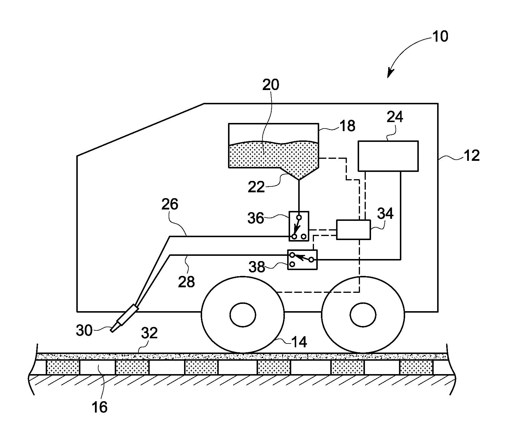
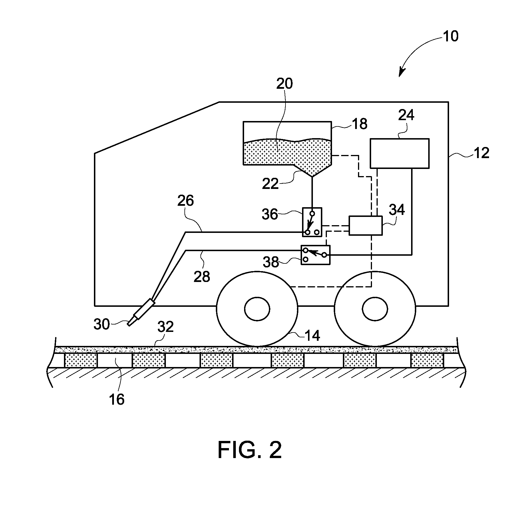
[0052]Embodiments of the invention relate to a tractive effort system for modifying the traction of a wheel contacting a surface, and associated methods.

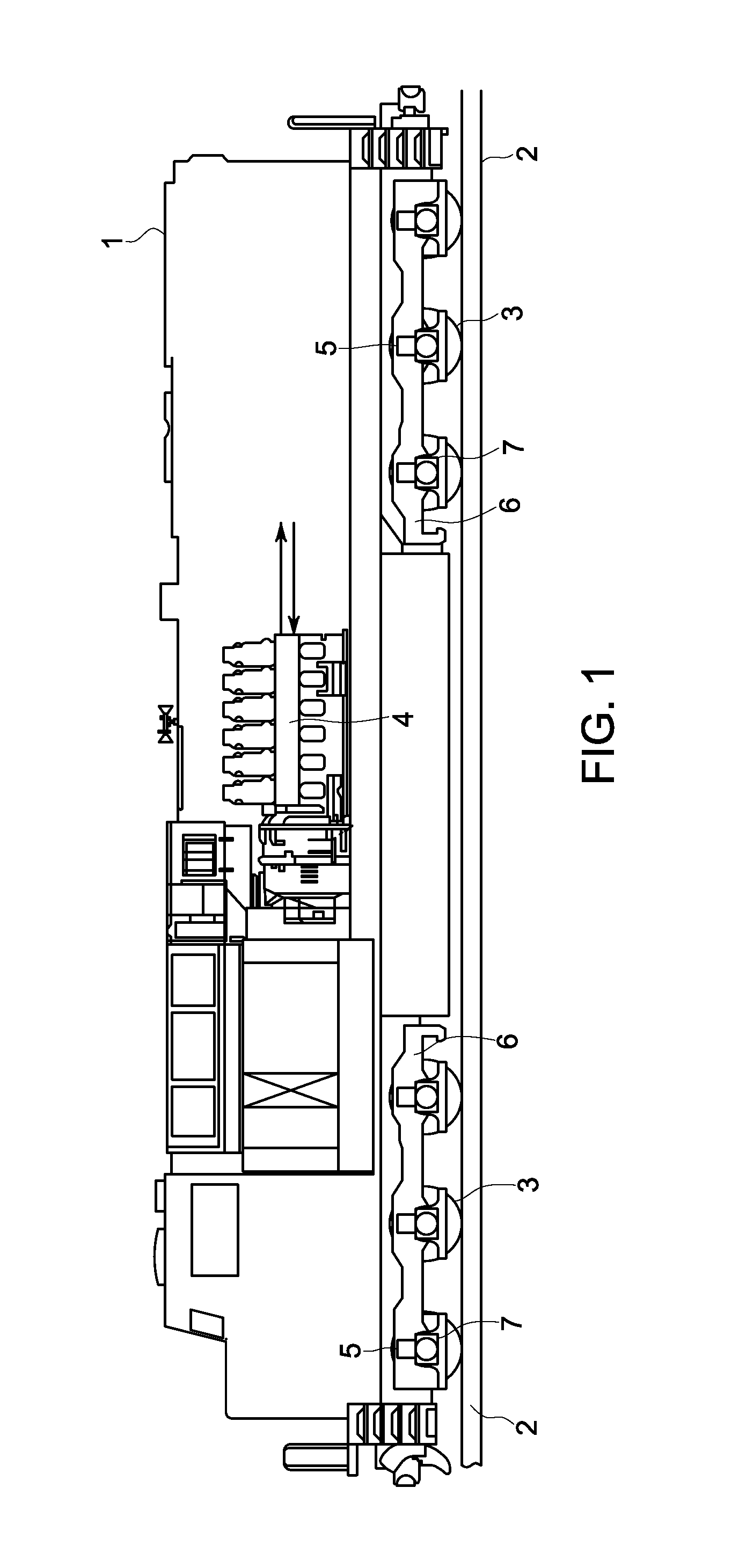
[0053]As used herein, “contact surface” means the area of contact on a surface that both is where a nozzle directs a stream of tractive material and where a portion of the surface will meet a wheel that is rolling over the surface; it is distinguished from the wheel / surface interface that, at any point in time, is where the wheel is actually contacting the surface. In exemplary instances, a surface can be a metal rail or pavement, and the wheel can be a metal wheel or a polymeric wheel. “Rail vehicle” can be a locomotive, switcher, shunter, and the like and includes both freight haulage and passenger locomotives, which themselves may be diesel electric or all electric, and that may run on either AC or DC electric power. “Debris” may mean leaves and vegetation, water, snow, ash, oil, grease, insect swarms, and other materials that ca...


PUM


Abstract

A system is provided for use with, a wheeled vehicle. The system includes a media reservoir capable of holding a tractive material that includes particulates; a nozzle in fluid communication with the media reservoir; and a media valve in fluid communication with the media reservoir and the nozzle. The media valve is controllable between a first state in which the tractive material flows through the media valve and to the nozzle, and a second state in which the tractive material is prevented from flowing to the nozzle. In the first state, the nozzle receives the tractive material from the media reservoir and directs the tractive material to a contact surface such that the tractive material impacts the contact surface that is spaced from a wheel/surface interface. The system can modify the adhesion or the traction capability of the contact surface with regard to a subsequently contacting wheel.

Description

CROSS REFERENCE TO RELATED APPLICATIONS[0001]This application claims the benefit of U.S. Provisional Application Ser. No. 61 / 371,886 filed on Aug. 9, 2010, which is herein incorporated by reference in its entirety.TECHNICAL FIELD[0002]Embodiments of the invention relate to a tractive effort system for modifying the traction of a wheel contacting a surface, and associated methods.DISCUSSION OF ART[0003]It is sometimes desired in the rail industry to increase the tractive force of a locomotive to facilitate the transport of large and heavy cargo. Tractive force is the pulling or pushing force exerted by a vehicle, machine or body. As used in the rail industry, tractive effort (which is synonymous with tractive force) is the pulling or pushing capability of a locomotive, i.e., the pull force a locomotive is capable of generating. Tractive effort further may be classified as starting tractive effort, maximum tractive effort and continuous tractive effort. Starting tractive effort is the...

Claims


Application Information

Patent Timeline
IPC IPC(8): B61C15/10
CPCB61C15/107B61C15/102
Inventor WORDEN, BRET DWAYNEKUMAR, AJITH KUTTANNAIRMALONE, MATTHEW JOHNCOYNE, JENNIFER LYNNTAMBE, NIKHIL SUBHASCHANDRAGARULE, MILIND BHARATKUMAR, ANUBHAV
Owner GE GLOBAL SOURCING LLC
Why Eureka
Try Eureka