Luminescent material and light emitting device comprising such luminescent material

a technology of luminescent materials and light emitting devices, which is applied in the field of luminescent materials, can solve the problems of low conversion efficiency, low photochemical stability, low chemical stability, etc., and achieve the effect of intense and efficient uvc emission

Inactive Publication Date: 2013-08-15
SIGNIFY HLDG BV
View PDF16 Cites 8 Cited by
  • Summary
  • Abstract
  • Description
  • Claims
  • Application Information

AI Technical Summary

Benefits of technology

[0013]It is another object of the present invention to provide a light emitting device comprising luminescent materials, which device shows intense and efficient UVC emission with a spectral power distribution that fits well to the germicid

Problems solved by technology

Presently applied UV luminescent materials for these Xe, Ne, or Xe/Ne excimer lamps still have a couple of drawbacks, for example, inc

Method used


Image

  • Luminescent material and light emitting device comprising such luminescent material
  • Luminescent material and light emitting device comprising such luminescent material
  • Luminescent material and light emitting device comprising such luminescent material

Examples


example i

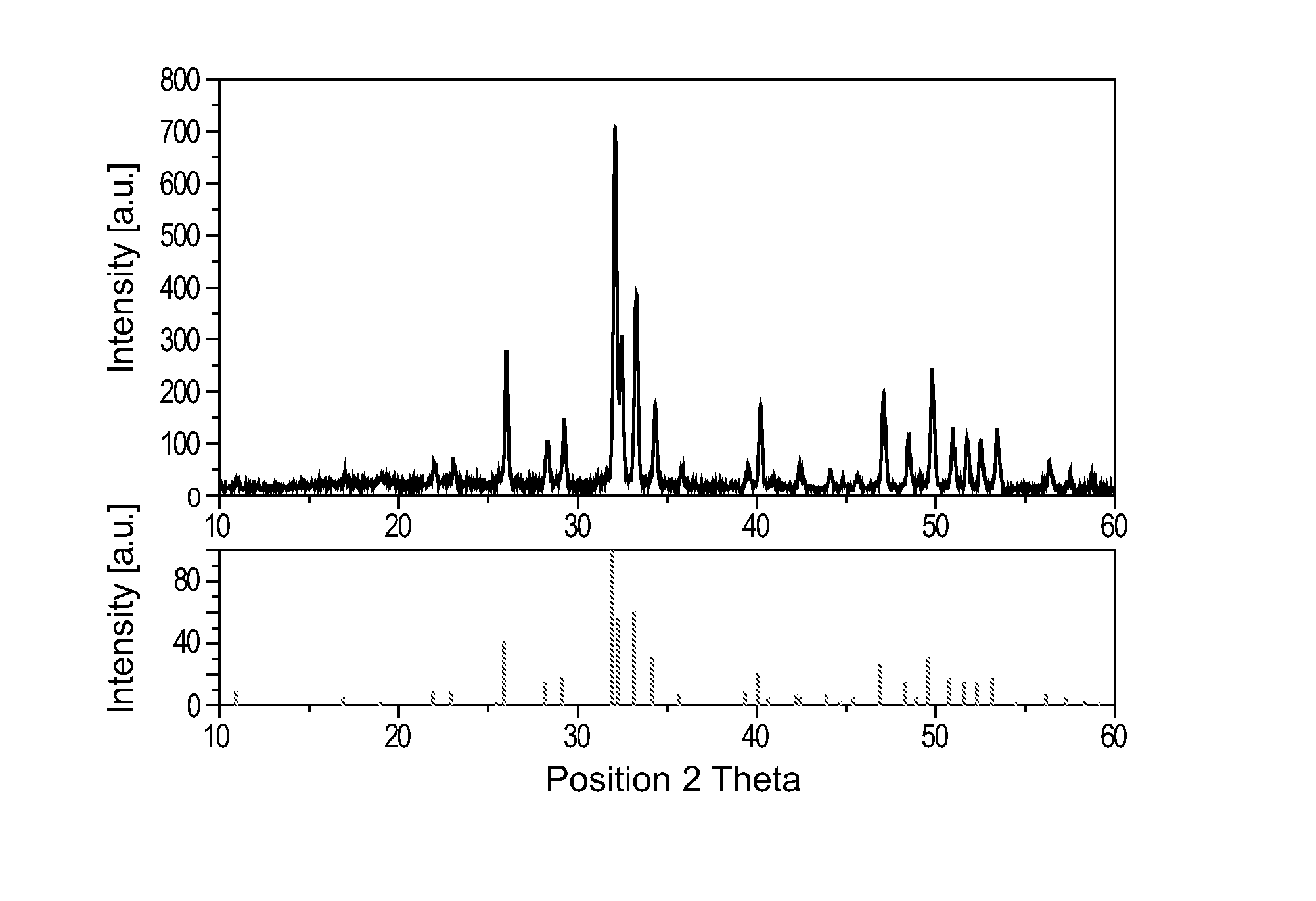
[0041]Example I refers to Ca5(PO4)3F:Pr3+ (1%)Na+ (1%), which can be made in the following way:

[0042]The starting materials 1.009 g CaCO3, 4.0004 g CaHPO4.2H2O, 0.32 g nanoscale CaF2, and 0.076 g PrF3 and 0.016 g NaF have been milled for 0.5 hours. The blend has been subsequently annealed at around 1100° C. under Nitrogen for 1 hour. Finally, the material is milled and sieved through a 36 μm sieve.

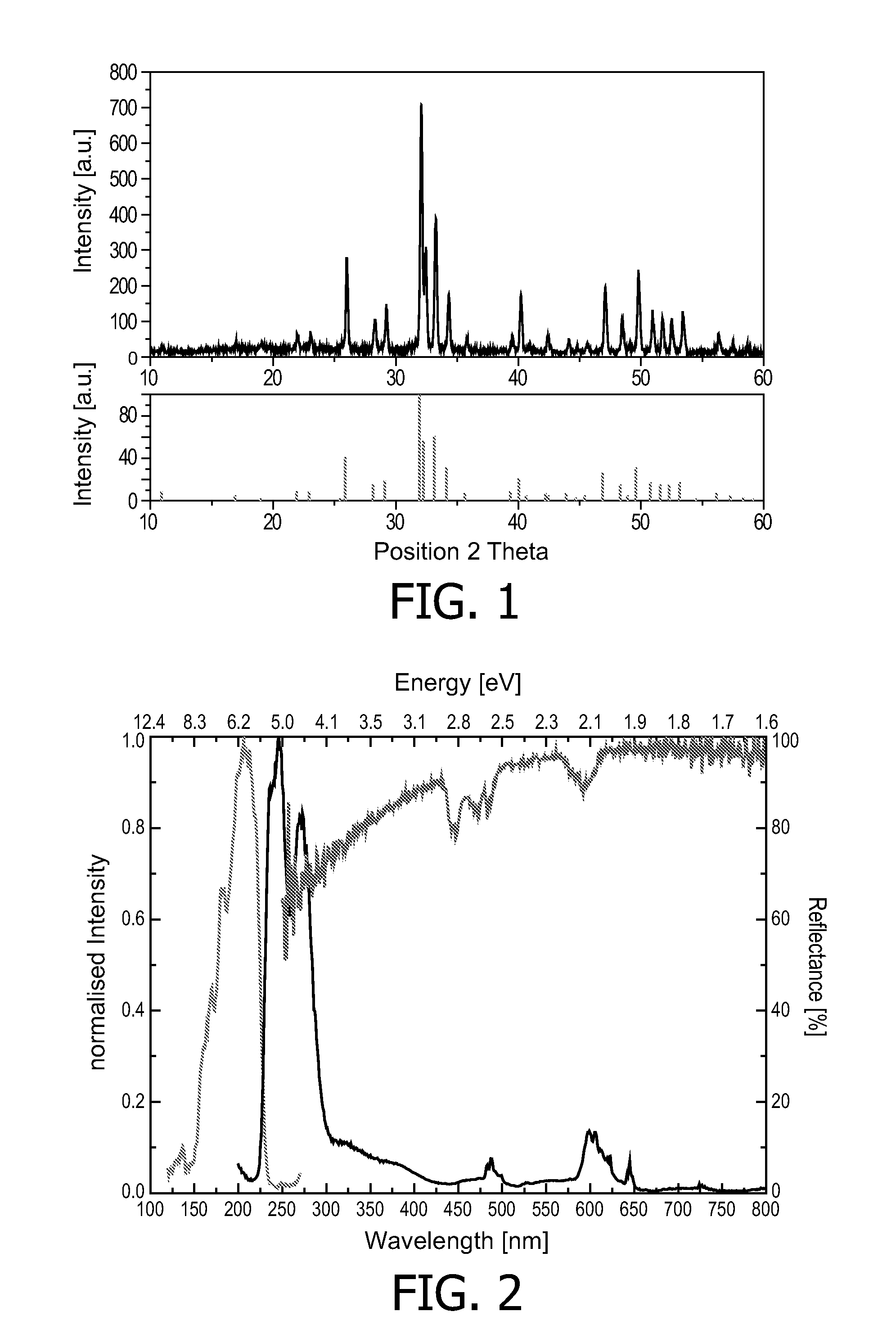
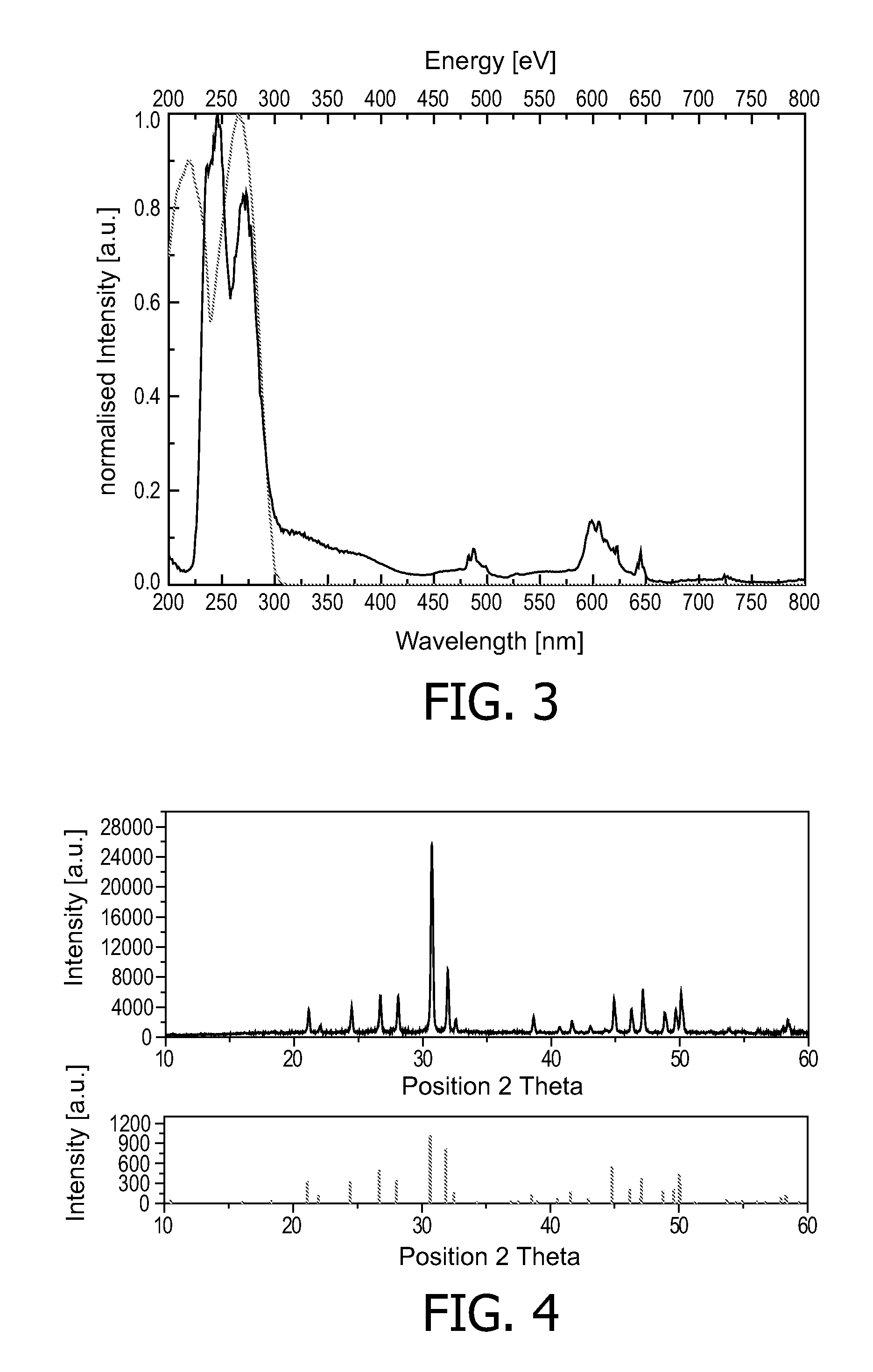
[0043]FIG. 1 shows an XRD pattern of the material of Example I. FIG. 2 shows the excitation spectrum (left spectrum), the emission spectrum (right spectrum) and the reflection spectrum (upper right spectrum) of the material of Example I. FIG. 3 shows a comparison between the emission spectrum (the curve with relatively narrow extension along the wavelength in the drawing, as well as in other drawings of the same type referred to below) of the material of Example I and the desired spectrum of the germicidal action. The emission maximum of Ca5(PO4)3F:Pr,Na is at around 245 nm, which shows a ...

example ii

[0044]Example II refers to Sr5(PO4)3F:Pr3+ (1%)Na+ (1%), which can be made in the following way:

[0045]The starting materials 5.036 g SrCO3, 2.675 g (NH4)2HPO4.2H2O, 0.487 g nanoscale SrF2, and 0.076 g PrF3 and 0.016 g NaF have been milled for 0.5 hours. The blend has been subsequently annealed at around 1100° C. under Nitrogen for 1 hour. Finally, the material is milled and sieved through a 36 μm sieve.

[0046]The emission maximum of Sr5(PO4)3F:Pr,Na is at about 240 nm, which also shows a good overlap with the germicidal action curve. It can clearly be seen from FIGS. 4-6 that this material is an excellent material for use in discharge lamps for UV-C radiation.

example iii

[0047]Example III refers to Y9LiSi6O26:Pr3+ (1%), which can be made in the following way:

[0048]The starting materials 4.000 g Y2O3, 0.147 g Li2CO3, 1.433 g nanoscale SiO2, and 0.061 g Pr6O11 are suspended in ethanol and the material is ground until the solvent has completely evaporated. Afterwards, the dried material is fired at 1000° C. under CO for 6 hours and subsequently ground and fired at 1100° C. under CO for 6 hours. Finally, the material is milled and sieved through a 36 μm sieve. It can clearly be seen from FIGS. 7-8 that this material is an excellent material for use in discharge lamps for UV-C radiation.


PUM


Abstract

The invention provides a luminescent material comprising a component selected from the group comprising (Y1-xLux)9LiSi6O26:Ln or/and AE5(PO4)3F:Ln,A, wherein Ln is a trivalent rare earth metal, AE is a divalent alkaline earth metal, and A is a monovalent alkaline metal, x>0.0 and <1.0. The luminescent material has an emission peak in the UV-C range when being excited by light in the UV spectrum range. The invention further provides a light emitting device comprising the said luminescent material and a method of using said light emitting device for disinfection or purification of air, water or surfaces.

Description

FIELD OF THE INVENTION[0001]The present invention relates to luminescent material, especially to the field of luminescent material for light emitting devices emitting UV radiation.BACKGROUND OF THE INVENTION[0002]UV radiation sources have found many application areas, such as spectroscopy, cosmetic skin treatment, medical skin treatment, disinfection or purification of water and air, polymer hardening, photochemistry, surface curing, and wafer processing.[0003]Many of the above mentioned application areas require deep UV radiation, i.e. UV-C (200-280 nm) or even VUV radiation (100-200 nm), wherein fast switching cycles and invariance against temperature changes are desired features.[0004]Low-pressure Hg discharge lamps are currently widely used as UV radiation sources and they have an emission spectrum which is dominated by two lines, viz. at 185 and 254 nm. However, increasing the Hg vapor pressure may result in an almost continuous spectrum extending from the deep UV to the deep r...

Claims


Application Information

Patent Timeline
IPC IPC(8): C09K11/77H01J61/35A61L2/10F21Y101/00
CPCC09K11/7711C09K11/7774H01J61/44H01J61/35A61L2/10C09K11/7706H01L33/502C09K11/55F21S13/00F21Y2101/00C09K11/7758
Inventor GREUEL, GEORGJUSTEL, THOMASBETTENTRUP, HELGAPLEWA, JULIAN
Owner SIGNIFY HLDG BV
Why Eureka
Try Eureka