Modular stackable shelving framework and equipment storage system

a technology of shelving framework and modular structure, which is applied in the direction of casings/cabinets/drawers, casings/cabinets/drawers, instruments, etc., can solve the problems of adding considerable weight and mass to the overall electric component, affecting the design of equipment chassis and rack cabinet architecture, and requiring a large amount of assembly

Active Publication Date: 2013-08-15
ARA USA LLC
View PDF3 Cites 23 Cited by
  • Summary
  • Abstract
  • Description
  • Claims
  • Application Information

AI Technical Summary

Benefits of technology

[0033]According to another aspect, a method of making a module for a modular storage system is provided. The method comprises: providing a top panel and a bottom panel, each of the top panel and bottom panel comprising first and second opposed edges; providing first and second side members, each of the first and second side members comprising a top edge and a bottom edge; attaching the top edges of the first and second

Problems solved by technology

Rack mountable electric appliance chassis are typically constructed of steel sheet metal which adds considerable weight and mass to the overall electric component.
A difficulty of such a cabinet system is that the cabinet is typically shipped in assembled form with a significant cost of shipping at a fixed standard height to fit through the average door.
Many other difficulties also exist between the independent design requirements of equipment chassis and rack cabinet architectures.
Although the typical steel box construction of each rack mountable equipment chassis is very rigid and crush resistant, once mounted into the equipment rack, the mass of the chassis becomes surplus weight that must

Method used


Image

  • Modular stackable shelving framework and equipment storage system
  • Modular stackable shelving framework and equipment storage system
  • Modular stackable shelving framework and equipment storage system

Examples


Embodiment Construction

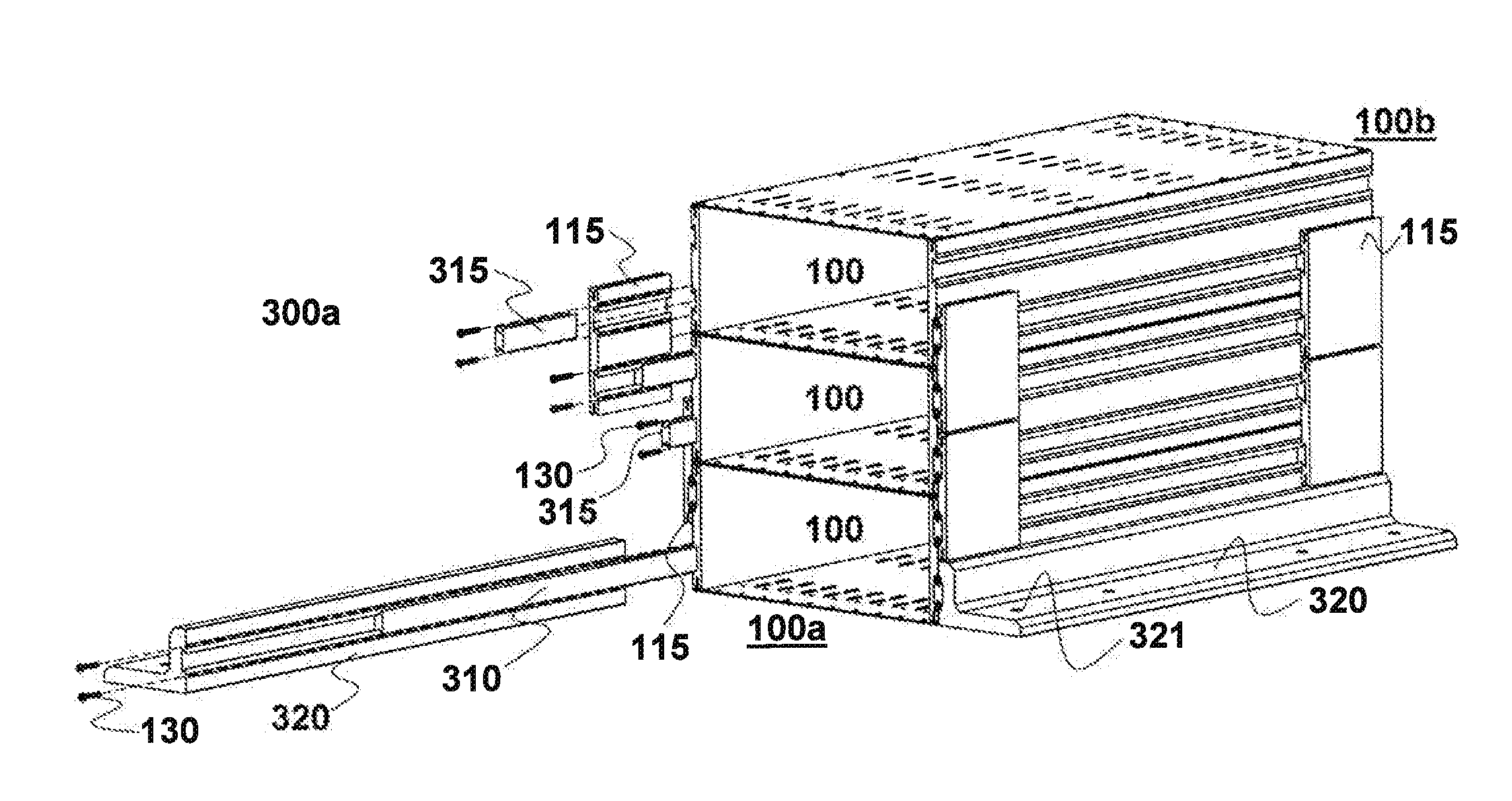
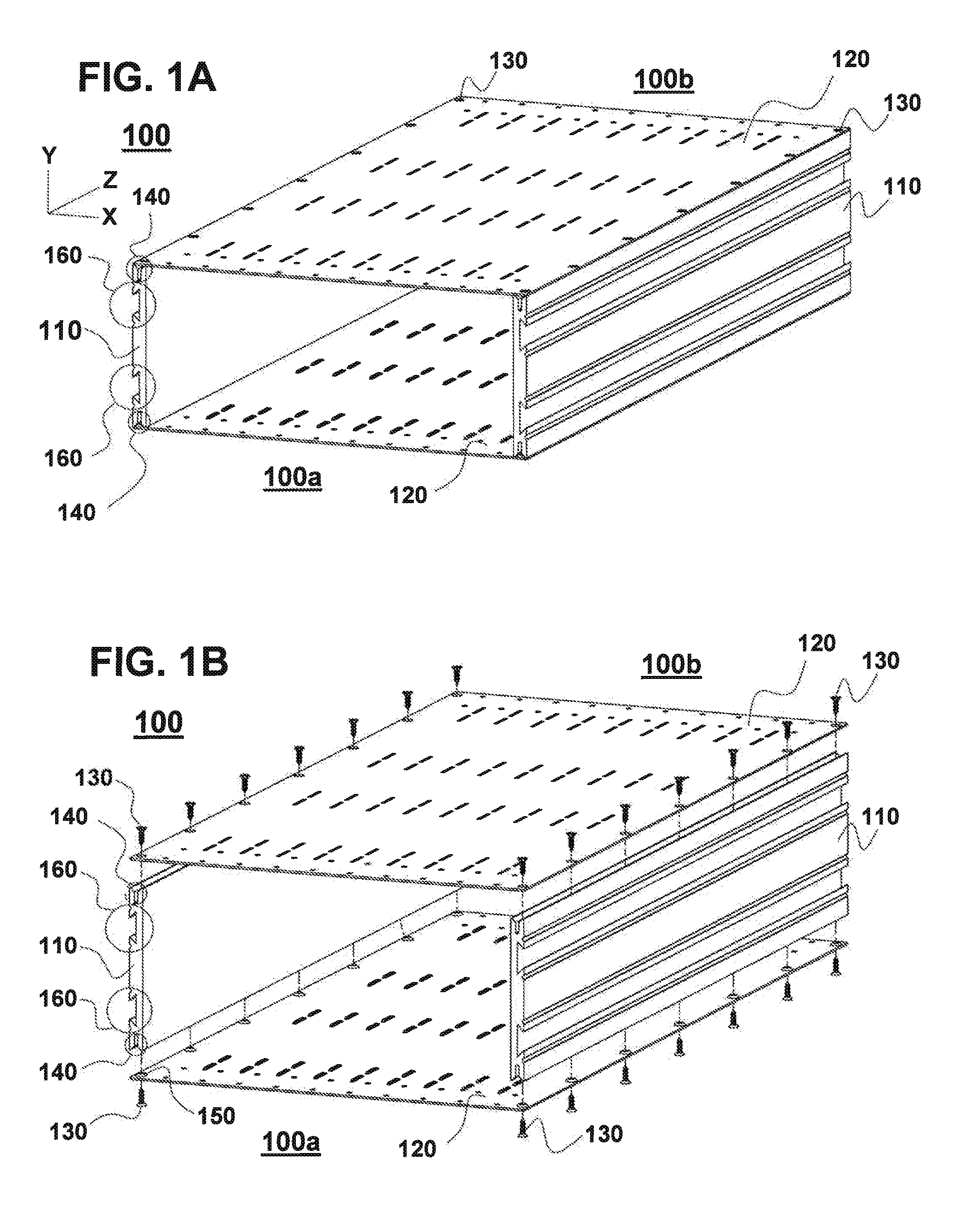
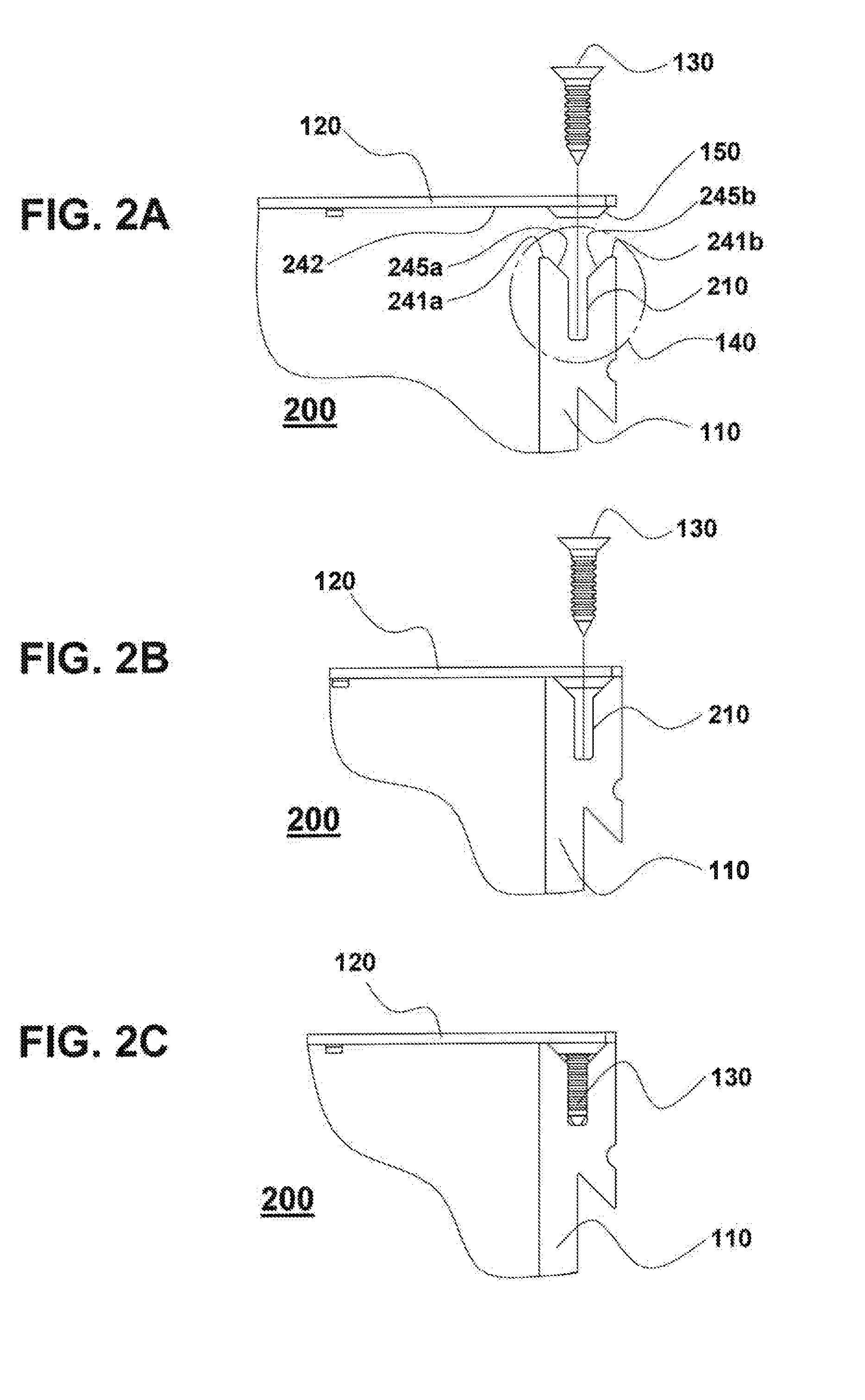
[0049]The present description relates to shelving systems and equipment storage management and more particularly to a structurally integrated building-block shelf frame system for storing electronic and non-electronic equipment subframes that can be mechanically interconnected with minimal labor content to assemble the resultant structure without the requirement of equipment racks or equipment rack cabinets. The present description is given to enable one of ordinary skill in the art to make and use the invention and is provided in the context of a patent application and its requirements. Various modifications to the embodiments described herein and the generic principles and features described herein will be readily apparent to those skilled in the art. For instance, although a finite number of shelf frame structure configurations are illustrated in the embodiments, it is clear that any number or even one shelf frame unit could be utilized.

[0050]In accordance with some embodiments, ...


PUM

PropertyMeasurementUnit
Lengthaaaaaaaaaa
Shapeaaaaaaaaaa
Mechanical propertiesaaaaaaaaaa

Abstract

A modular storage system and method, a module and a method of making the same include a top panel and a bottom panel, each of the top panel and bottom panel comprising first and second opposed edges, and first and second side members. Each of the first and second side members comprises: a top edge and a bottom edge, the top edges of the first and second side members being attached to the opposed edges of the top panel, and the bottom edges of the first and second side members being attached to the opposed edges of the bottom panel; and a longitudinal attachment feature running along a length of the side member along a longitudinal axis of the side member, longitudinal attachment features of first and second modules enabling coupling together of the first and second modules.

Description

BACKGROUND[0001]1. Field of Invention[0002]The present invention relates to shelving systems and equipment storage management and more particularly to a structurally integrated building-block shelf frame system for storing electronic and non-electronic equipment that can be mechanically interconnected with minimal labor content to assemble the resultant structure without the requirement of equipment rack cabinets.[0003]2. Discussion of the Prior Art[0004]Datacenters are designed and constructed to optimize power and cooling requirements for a plurality of electric components such as power supplies, memory units, network appliances and servers. Since their introduction into datacenters, most of these electric devices have been adapted to fit into rack mountable appliance chassis. Rack mountable electric appliance chassis are typically constructed of steel sheet metal which adds considerable weight and mass to the overall electric component. In datacenters, the steel appliance chassis...

Claims


Application Information

Patent Timeline
IPC IPC(8): H05K7/20B23P11/00H05K5/02H05K7/00A47B87/00
CPCH05K7/1488Y10T29/49826A47B87/0276H05K5/0021H05K5/0247H05K7/023H05K7/14H05K7/183H05K7/20
Inventor FRANKLIN, BARRETT W.
Owner ARA USA LLC
Why Eureka
Try Eureka