Wireless communication system and wireless communication method

a wireless communication and wireless communication technology, applied in the field of wireless communication system and wireless communication method, can solve the problems of further deterioration of property and the upper limit of actual throughput, and achieve the effects of improving channel information accuracy, reducing interference, and reducing interference resistan

Active Publication Date: 2013-08-15
NIPPON TELEGRAPH & TELEPHONE CORP
View PDF5 Cites 58 Cited by
  • Summary
  • Abstract
  • Description
  • Claims
  • Application Information

AI Technical Summary

Benefits of technology

[0051]As described above, in accordance with the present invention, even if there is interference due to low accuracy of channel information, a null is directed to a terminal, interference in the terminal is detected, and channel estimation is performed again to re-acquire channel information when the terminal is determined to suffer from the interference, thereby improving the accuracy of the channel information and mitigating the interference.
[0052]Moreover, even if there is interference due to low accuracy of channel information, interference due to another base station or another wireless communication system, or the like, the interference amount is measured and communication with increasing interference resistance in accordance with the interference amount is performed, thereby mitigating the influence of the interference.
[0053]Furthermore, when transmissions to a plurality of communication parties are performed at the same time using the same frequency through a spatial multiplexing scheme, it is possible to evaluate the inter-user interference and appropriately select a modulation scheme, a coding rate, and the number of spatial streams for each terminal.

Problems solved by technology

In fact, since the transmission efficiency in a MAC (medium access control) layer is about 50 to 70%, an upper limit of the actual throughput is about 30 Mbps and this property is further deteriorated when communication parties requiring information increase.

Method used


Image

  • Wireless communication system and wireless communication method
  • Wireless communication system and wireless communication method
  • Wireless communication system and wireless communication method

Examples


first embodiment

A. First Embodiment

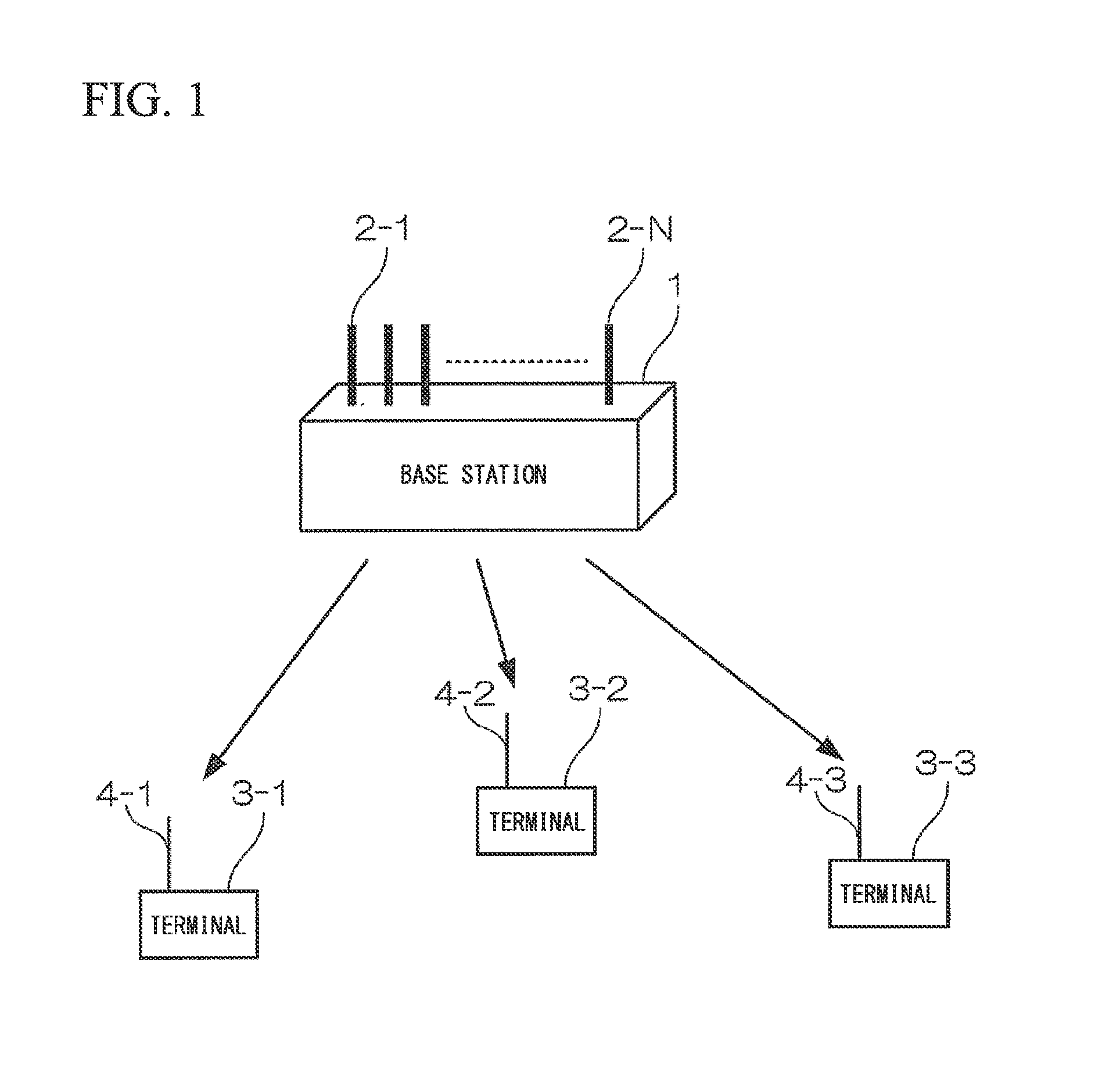
[0087]FIG. 1 is a block diagram illustrating a configuration of a wireless communication system in accordance with a first embodiment of the present invention. The wireless communication system includes one base station 1 and three terminals 3-1 to 3-3. The base station 1 has N (N≧3) antennas 2-1 to 2-N, and the terminals 3-1 to 3-3 have antennas 4-1 to 4-3, respectively. An OFDM (orthogonal frequency division multiplexing) scheme is used as a communication scheme. The base station 1 and the terminals 3-1 to 3-3 each acquire a transmission right through CSMA / CA (carrier sense multiple access with collision avoidance) access control and transmit a packet. After acquiring the transmission right, the packet is transmitted using MU-MIMO from the base station 1 to the terminals 3-1 to 3-3. The terminals 3-1 to 3-3 have unique identifiers.

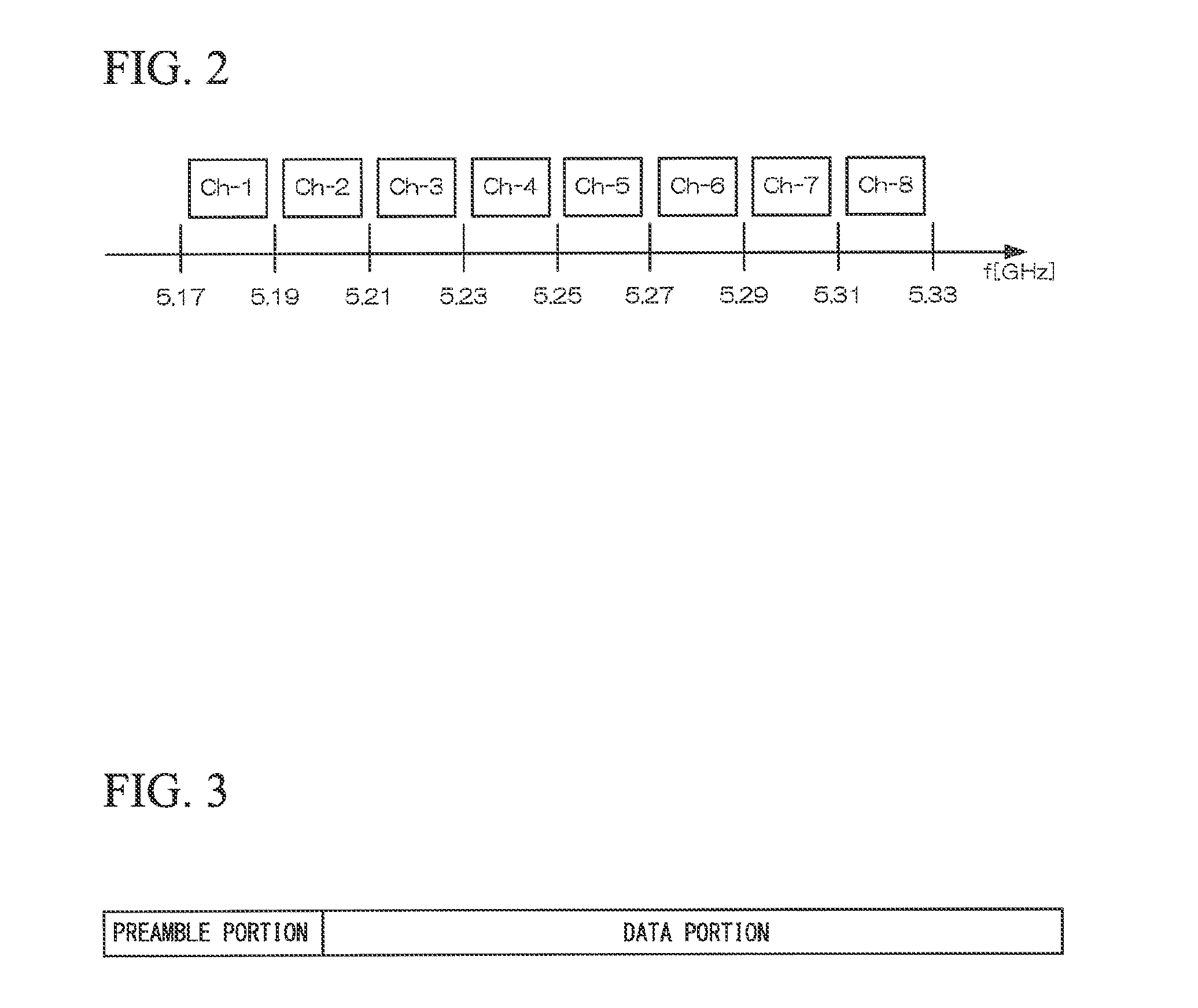
[0088]FIG. 2 is a conceptual diagram illustrating a channel configuration of the wireless communication system in accordance with the...

second embodiment

B. Second Embodiment

[0129]In the first embodiment described above, the terminal to which the null is directed is periodically switched; however, the present invention is not limited thereto, and when there is no application data to be transmitted from the base station 1 to any one of the terminals 3-1 to 3-3, a null is directed to this terminal, making the same process as that of the first embodiment possible. In the first embodiment, since a terminal receives no application data while the null is being directed to the terminal, the throughput is reduced; in contrast, in the present second embodiment, since the terminal to which the null is being directed need not originally receive the application data, the throughput of the entire system is not reduced.

third embodiment

C. Third Embodiment

[0130]In the first and second embodiments described above, the application packet is transmitted from the base station 1 to the terminals 3-1 to 3-3 at the same time using the MU-MIMO scheme. As described previously, in the MU-MIMO scheme, when the accuracy of the channel information is low, interference occurs between the terminals. Thus, in the present third embodiment, a terminal having low accuracy of channel information is excluded from a MU-MIMO transmission group, and an application packet is transmitted without using the MU-MIMO scheme, thereby avoiding the interference between the terminals.

[0131]FIG. 15 is a timing chart illustrating a packet control flow of a wireless communication system in accordance with the present third embodiment. For example, if an interference information packet is received from the terminal 3-1 (t6), the base station 1 excludes the terminal 3-1 from the MU-MIMO group, determines to transmit an application packet to the terminal...


PUM


Abstract

Communication quality is prevented from being deteriorated due to interference caused by low accuracy of channel information or interference from another base station or another wireless communication system. A wireless communication system includes a first wireless station including a plurality of antenna elements, transmission units corresponding to the plurality of antenna elements, and a transmission directivity control unit that controls transmission directivity of the plurality of antenna elements, and a plurality of second wireless stations each including a reception power measurement unit that measures a reception power. The transmission directivity control unit determines the transmission directivity of each of the plurality of antenna elements so that a signal does not reach a particular second wireless station among the plurality of second wireless stations. The transmission units generate wireless signals using the transmission directivity. The plurality of antenna elements transmit the generated wireless signals. The reception power measurement unit measures the reception power in a period that is set so that a signal does not reach the particular second wireless station, and detect the presence or absence of interference.

Description

TECHNICAL FIELD[0001]The present invention relates to a wireless communication system and a wireless communication method. The present invention particularly relates to a wireless communication system and a wireless communication method using space division multiple access control technology. Moreover, the present invention particularly relates to transmission technology in a wireless communication system that simultaneously communicates with a plurality of communication parties using spatial multiplexing.[0002]Priority is claimed on Japanese Patent Application No. 2010-256077, filed Nov. 16, 2010 and Japanese Patent Application No. 2011-088264, filed Apr. 12, 2011, the contents of which are incorporated herein by reference.BACKGROUND ART[0003]With recent developments such as those in the Internet, networks have been spreading to both homes and offices. Such a network is called a LAN (local area network). A wireless LAN that is a wireless version of the LAN has also been spreading. ...

Claims


Application Information

Patent Timeline
Patent Type & Authority Applications(United States)
IPC IPC(8): H04B7/04
CPCH04W16/28H04W24/10H04B7/0452H04B17/318H04L5/0053H04L5/0057H04B7/0617H04L5/0023H04B7/0632
Inventor KUDO, RIICHIMATSUI, MUNEHIROMURAKAMI, TOMOKIICHIKAWA, TAKEOASAI, YUSUKEISHIHARA, KOICHIYAMADA, TOMOYUKIMIZOGUCHI, MASATO
Owner NIPPON TELEGRAPH & TELEPHONE CORP
Why Eureka
Try Eureka