
Microphone apparatus and method for removing unwanted sounds

a microphone and unwanted sound technology, applied in the direction of transducer circuits, transducer casings/cabinets/supports, speech analysis, etc., can solve the problems of mechanical vibration, movement of the membrane, and other vibrations of the electronic device on the membrane of the microphone componen

Inactive Publication Date: 2013-08-15
NOKIA TECHNOLOGLES OY
View PDF2 Cites 62 Cited by
  • Summary
  • Abstract
  • Description
  • Claims
  • Application Information

AI Technical Summary

Benefits of technology

The patent describes an apparatus and method for detecting and modifying sound and vibration. The apparatus includes two transducers: one for detecting sound and another for detecting vibration and unwanted sound. The second transducer is less sensitive to acoustic signals than the first transducer. The first transducer can detect both sound and vibration, while the second transducer is more sensitive to vibration. The apparatus can also include a processor to modify the first signal based on the second signal. The technical effect of this invention is to provide a more accurate and responsive method for detecting and modifying sound and vibration.

Problems solved by technology

When capturing audio from the environment of the electronic device the membrane of the microphone component may be subject to other vibrations of the electronic device.
For example, structural born mechanical vibrations of the electronic device can cause movement of the membrane.
This means that mechanical vibrations such as handing of the electronic device, movement of other components within the electronic device or other external mechanical vibrations of the electronic device are represented as noise in the audio signal.
The noise in an audio signal not due to sound can therefore significantly deteriorate the audio signal which may result in a bad user experience.
However some electronic devices are small in size and the amount of space available within the electronic device to fit vibration dampening material is limited.
This means effectively isolating mechanical vibration from small and lightweight microphone components in small electronic devices can be difficult to achieve.
However, the differing masses of the back plate and membrane of the microphone component can cause a mismatch in the frequency response of the back plate and the frequency response of the membrane.
A frequency response mismatch can lead to poor noise cancelling performance.
Additionally the performance of the microphone component in an environment where the electronic device is not subject to mechanical vibrations may be degraded due to the floating back plate.
However, the acceleration sensors can have different vibration sensitivities from the microphone membrane component at various frequencies of mechanical vibration, which can lead to poor noise cancelling performance.
Furthermore production of a microphone component comprising both a membrane and an accelerometer can require non-optimal manufacturing solutions which may be costly.
However, if there is a change in one microphone output caused by temperature change, and the calibration function does not compensate, then the noise cancelling algorithm would not be performing as well as expected.
In fact, any condition that changes the sensitivities of the two microphones differently relative to the calibrated value will deteriorate the performance of the entire system.
This, however, is an imperfect solution for at least three reasons: 1) the microphone output signal is often already saturated by wind noise, 2) the demands of preferred audio quality in non-windy environment require the high-pass filter to be set at a point which will still pass a large proportion of the wind noise, and 3) this strategy is not possible with digital microphones.
Attempts have been made to use DSP circuitry to clean a windy signal from a multiple array of microphones but they have had limited effectiveness.

Method used


Image

  • Microphone apparatus and method for removing unwanted sounds
  • Microphone apparatus and method for removing unwanted sounds
  • Microphone apparatus and method for removing unwanted sounds

Examples


Embodiment Construction

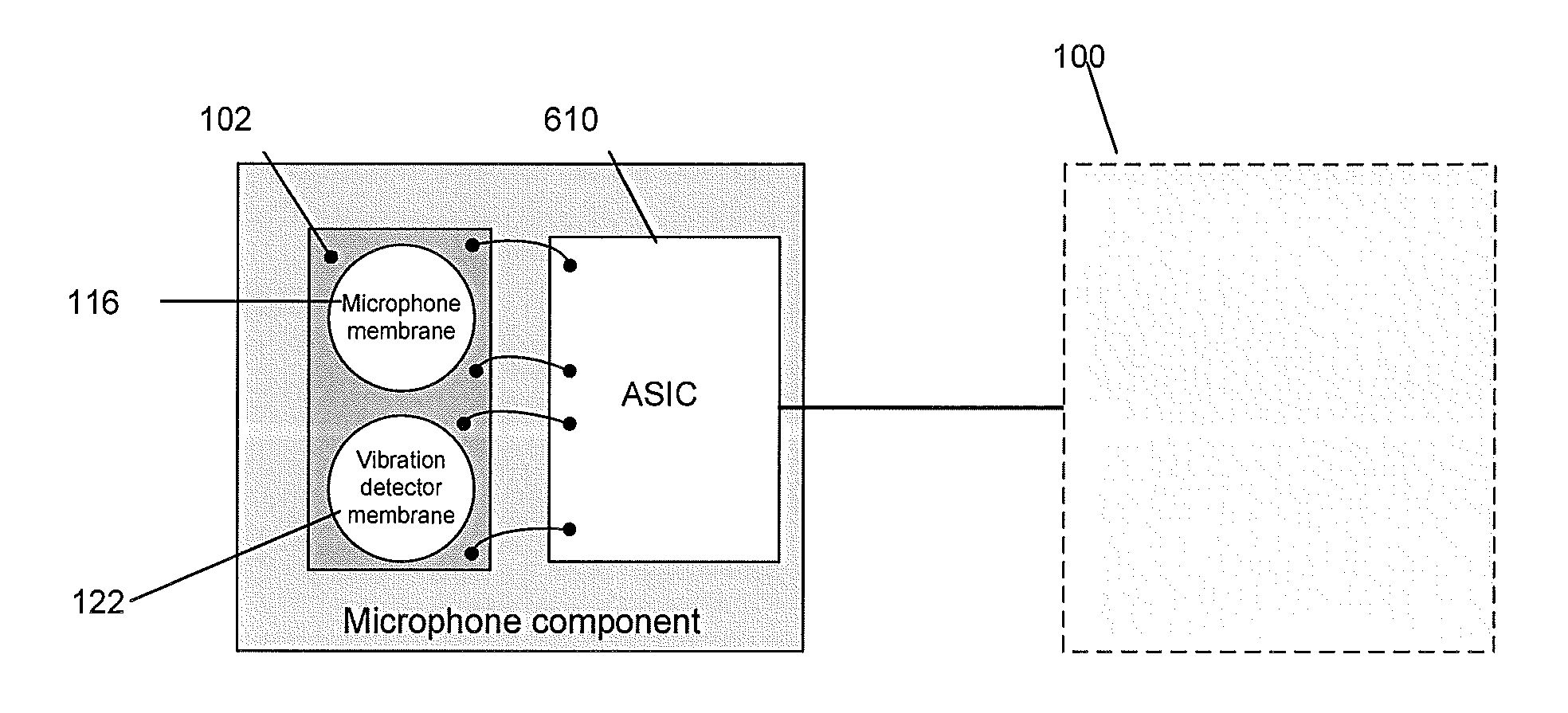
[0042]The following describes apparatus and methods for reducing the noise in an audio signal from mechanical vibrations experienced by an electronic device.

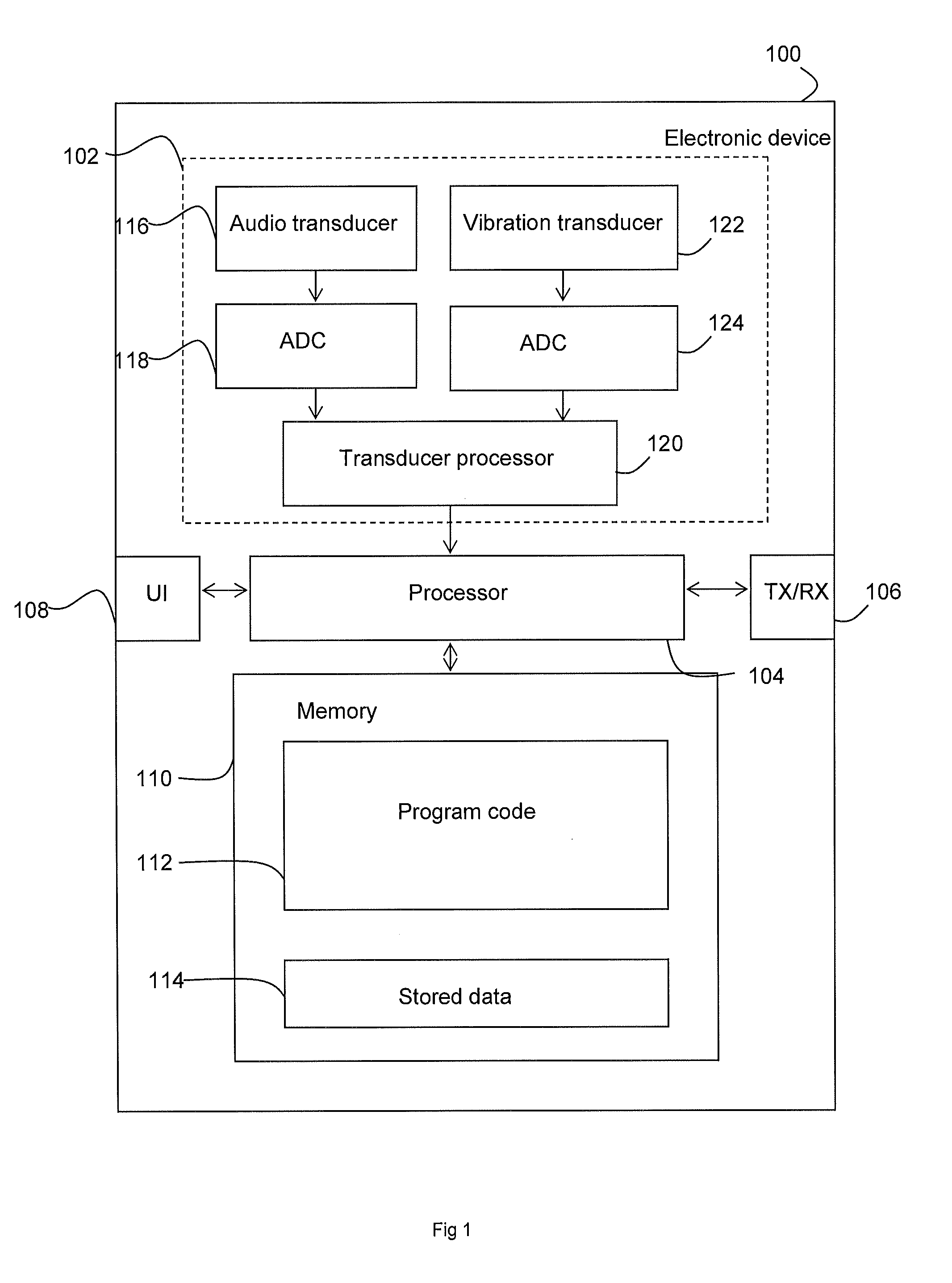
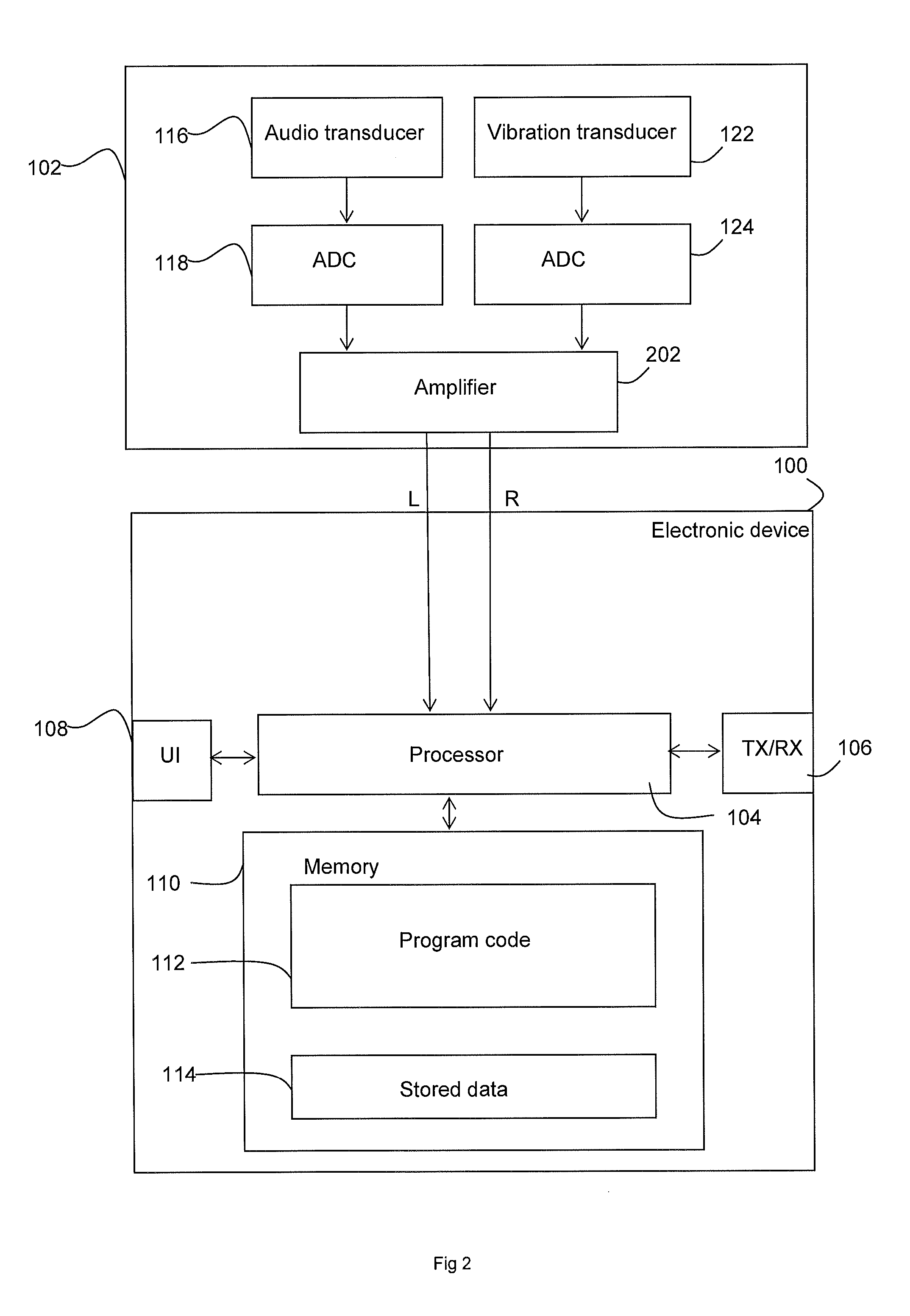
[0043]In this regard reference is made to FIG. 1 which discloses a schematic block diagram of an exemplary electronic device 100 or apparatus. The electronic device 100 is configured to reduce mechanical vibrations captured in an audio signal according to some embodiments.

[0044]The electronic device 100 is in some embodiments a mobile terminal, a mobile phone or user equipment for operation in a wireless communication system. In other embodiments, the electronic device is a digital camera, a camcorder, a portable dictation device, personal digital assistant (PDA), laptop or any other electronic device suitable for capturing sound.

[0045]The electronic device 100 comprises an audio module 102 which is linked to a processor 104. The processor 104 is linked to a transceiver (TX / RX) 106, to a user interface (UI) 108 and to memory 110...


PUM


Abstract

An apparatus comprises a first transducer configured to detect sound and generate a first signal based on the detected sound. The apparatus also comprises a second transducer configured to detect vibration and / or sound and generate a second signal based on the detected vibrations and / or sound. The second transducer is less acoustically responsive than the first transducer. The apparatus comprises an interface configured to send the first and second signals to a processor configured to modify the first signal on the basis of the second signal.

Description

FIELD OF THE APPLICATION[0001]The present application relates to a method and apparatus. In some embodiments the method and apparatus relate to a microphone component of an electronic device.BACKGROUND OF THE APPLICATION[0002]Some electronic devices comprise microphone components for capturing audio. A microphone component of an electronic device is typically integral with the electronic device and is located within the electronic device such that audio from the surrounding environment of the electronic device is captured.[0003]The microphone component of the electronic device may comprise a membrane which moves in response to sound incident thereon. The movement of the membrane is detected and circuitry of the microphone component may generate an audio signal.[0004]When capturing audio from the environment of the electronic device the membrane of the microphone component may be subject to other vibrations of the electronic device. For example, structural born mechanical vibrations ...

Claims


Application Information

Patent Timeline
Patent Type & Authority Applications(United States)
IPC IPC(8): H04R3/00G10L21/0216
CPCG10L21/0216H04R2410/05H04R3/005H04R2201/003G10L21/02H04R1/02H04R3/00G10K2210/129
Inventor SUVANTO, MIKKO VELI AIMO
Owner NOKIA TECHNOLOGLES OY
Learn More