Floodgate

a floodgate and floodgate technology, applied in the field of floodgates, can solve the problems of pneumatic cylinders employing paper gaskets, which may also be damaged by condensate, and achieve the effect of fast setup time for floodgate systems

Inactive Publication Date: 2013-08-15
PARAFOIL DESIGN & ENG PTE
View PDF12 Cites 26 Cited by
  • Summary
  • Abstract
  • Description
  • Claims
  • Application Information

AI Technical Summary

Benefits of technology

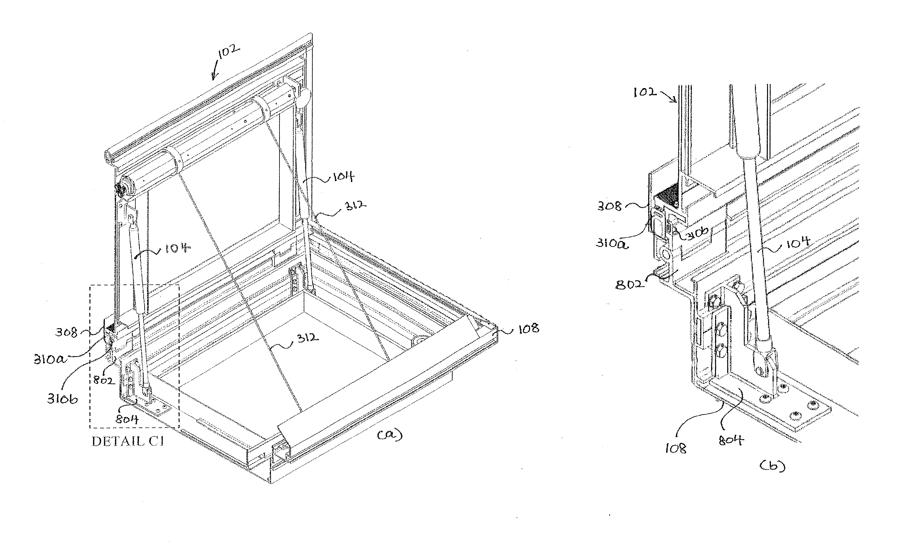
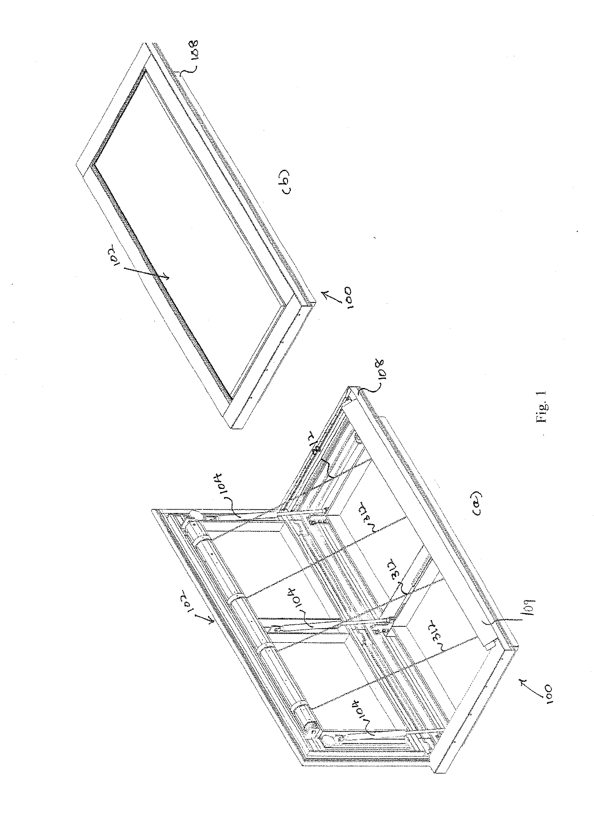
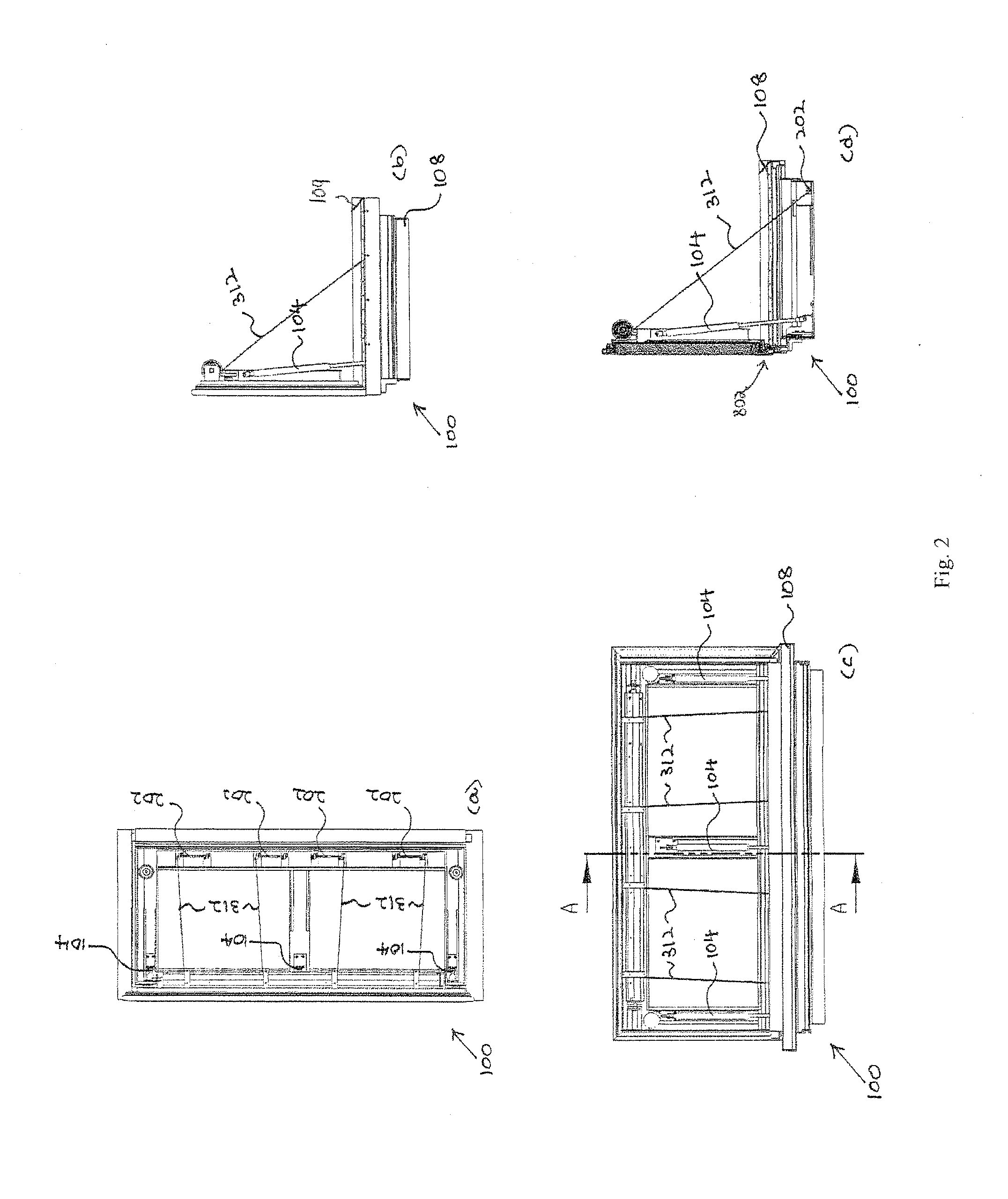
[0009]A gas strut is a set of elongate members (usually two members) which are relatively slidable (e.g. by a telescoping motion) between a compressed configuration and an extended configuration. The gas strut includes a trapped amount of gas which is compressed in the compressed configuration and urges the gas strut into the extended configuration. It is advantageous to use gas struts to move the panel from the closed position to the opened position in the floodgate. Unlike hydraulic pumps which require motor pump oil and power supply, gas struts can be operated without the use of electrical power supply. Furthermore, no external air pump is required to operate a gas strut. This is advantageous over pneumatic cylinders which require an external air compressor. In highly humid areas, a large amount of condensate forms in a pneumatic cylinder. The mixture of this condensate with lubrication oil existing in the pneumatic cylinder can often damage the cylinder. Furthermore, pneumatic cylinders employ paper gaskets which may also be damaged by the condensate.
[0010]A second aspect of the invention is a floodgate comprising a frame for installation at a chosen location (e.g. in a floor), a panel connected to the frame by a hinge, and connection means (e.g. a bracket) for connecting at least one gas strut to the frame for opening the panel, whereby the gas strut acts on a movable portion of the panel, and the frame maintains the relative positions of the hinge and the connection means, thereby preventing transmission of force generated by the gas strut to the location.
[0013]In the floodgate system in the third aspect of the present invention, due to the overlapping sealing elements which close the gaps between the panels of the floodgates, a continuous barrier can be formed. Hence, no additional barriers (e.g. vertical posts) are required between the panels of the floodgates when the floodgate system is activated and a faster setup time for the floodgate system can be achieved.

Problems solved by technology

The mixture of this condensate with lubrication oil existing in the pneumatic cylinder can often damage the cylinder.
Furthermore, pneumatic cylinders employ paper gaskets which may also be damaged by the condensate.

Method used


Image

  • Floodgate
  • Floodgate
  • Floodgate

Examples


second embodiment

[0065]FIG. 10(a) and (b) are views of a floodgate 100b which is a variation of the floodgate 100, and which is the invention. FIG. 10(a) illustrates the floodgate 100b when the floodgate 100b is activated, whereas FIG. 10(b) illustrates the floodgate 100b when the floodgate 100b is deactivated. The floodgate 100b has a construction very similar to the floodgate 100, so like elements are given the same reference numerals. In contrast to the floodgate 100, the floodgate 100b has a steel frame 503 supporting a steel plate 501, on which are formed a wire mesh 505 and a top layer 507 which may be concrete, tile or stone. The steel plate 501 and frame 503 give the floodgate 100b additional strength to support a vehicle passing over the floodgate 100b when the floodgate 100b is deactivated.

third embodiment

[0066]FIG. 11 illustrates perspective views of a floodgate 1000 which is another variation of the floodgate 100 and which is the invention. FIG. 11(a) illustrates the floodgate 1000 when the floodgate 1000 is activated whereas FIG. 11(b) illustrates the floodgate 1000 when the floodgate 1000 is deactivated. FIGS. 12 and 13 respectively illustrate a cross-sectional side view of the floodgate 1000 when the floodgate 1000 is deactivated and a cross-sectional side view of the floodgate 1000 when the floodgate 1000 is activated. The floodgate 1000 is similar to the floodgate 100 and thus, the same parts will have the same reference numerals with the addition of prime.

[0067]The floodgate 1000 works in the same manner as the floodgates 100, 100b. However, unlike the floodgates 100, 100b which comprise a plurality of tubular drives 202, each with an integrated locking member, the floodgate 1000 comprises a plurality of stand-alone locking members in the form of electromagnetic locks 1102 (s...


PUM


Abstract

A floodgate is disclosed. The floodgate comprises a panel configured to be movable between an opened position and a closed position wherein in the opened position, the panel forms a barrier against flood water; and at least one gas strut configured to move the panel from the closed position to the opened position.

Description

FIELD OF THE INVENTION[0001]The present invention relates to a floodgate and a floodgate system comprising a plurality of floodgates.BACKGROUND OF THE INVENTION[0002]Hurricanes, typhoons, thunderstorms, tropical storms and torrential rain often lead to an increase in the rate of rainfall, an increase in the length of time the rainfall lasts and an increase in the total amount of rainfall. Many infrastructure flood control and land / mud slide prevention measures may not be effective against such increased rainfall. Although this may be overcome through infrastructure development (for example, infrastructure development to improve drainage of excess water), such development requires time and may not be sufficient or effective.[0003]Floods caused by such increased rainfall often lead to a huge amount of damages, losses, disruptions and inconveniences. For example, a flood developed within an underground carpark due to an excessive amount of water entering the carpark often results in th...

Claims


Application Information

Patent Timeline
Patent Type & Authority Applications(United States)
IPC IPC(8): E02B7/54E02B7/20
CPCE04H9/145E02B7/20E02B7/54E05F15/627E06B2009/007E05F15/53E05Y2201/654Y02A50/00
Inventor QUEK, JWEE THIAM
Owner PARAFOIL DESIGN & ENG PTE
Why Eureka
Try Eureka