Ball with camera for reconnaissance or recreation and network for operating the same

a ball and camera technology, applied in the field of ball with camera for reconnaissance or recreation and network for operating the same, can solve the problems of inability to change its own trajectory, and inability to adapt to the environmen

Active Publication Date: 2013-08-15
HOLLINGER STEVEN J
View PDF7 Cites 193 Cited by
  • Summary
  • Abstract
  • Description
  • Claims
  • Application Information

AI Technical Summary

Benefits of technology

[0062]In another aspect, a deformation on the camera ball housing, such as an indentation, aligns a user's finger relative to the axis of rotation for the purpose of introducing gyroscopic stability, and for providing the user's finger with a mechanical advantage accelerating the ball into its trajectory.

Problems solved by technology

This resilient object is further disadvantaged by its inability to change its own trajectory.
The inflatable housing and cubic shape of the preferred embodiment present impractical aerodynamic impediments with respect to drag if a pitched or projected airborne trajectory is desired.
As with the resilient object of patent GB2444391, this ball is disadvantaged by its inability to store and analyze successive frames of captured image data.
The ball is further disadvantaged by its inability to capture successive frames of image data captured while spinning or precessing past a ground-based subject in order to produce a meaningful video stream.
This ball is further disadvantaged by its inability to change its own trajectory.
This patent is disadvantaged by requiring external surface-mounted fins to ensure that the camera provides images from a desirable orientation.
This patent is disadvantaged by requiring an external surface-mounted aerodynamic tail to ensure that the camera provides images from a desirable orientation.
Golf ball dimples produce an undesirable drag at lower windspeeds.
Similarly, the rigid ridges on the upper surface of a Frisbee flying disc produce a desirable increase in lift over a significant portion of the disc's airborne trajectory, but produce an undesirable increase in drag at other portions of the disc's trajectory.
Such balls are disadvantaged by an inability to purposefully control their trajectory.
Projectile cameras of prior art are limited in their ability to generate images acquired in all directions from a single viewpoint, at one moment in time.
Such a limitation makes difficult, for example, the capture of a spherical panoramic video from a central point of view surrounded in all directions by moving objects.
Cameras of prior art, including examples of camera networks, are further disadvantaged by cumbersome camera housings, complex mechanics necessary for locomotion or flight, and costly guidance technology necessary for self-sustained flight.

Method used


Image

  • Ball with camera for reconnaissance or recreation and network for operating the same
  • Ball with camera for reconnaissance or recreation and network for operating the same
  • Ball with camera for reconnaissance or recreation and network for operating the same

Examples


Embodiment Construction

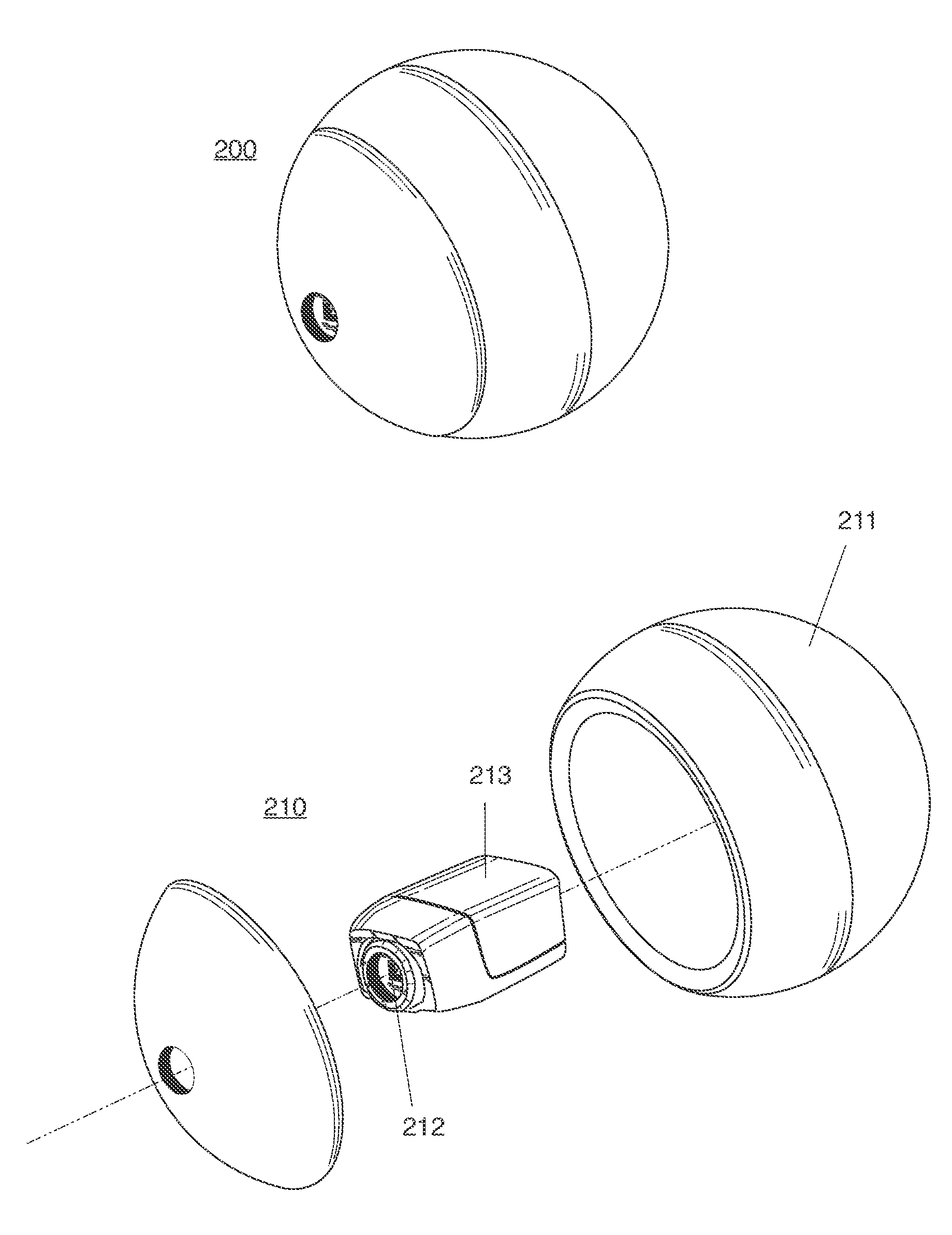
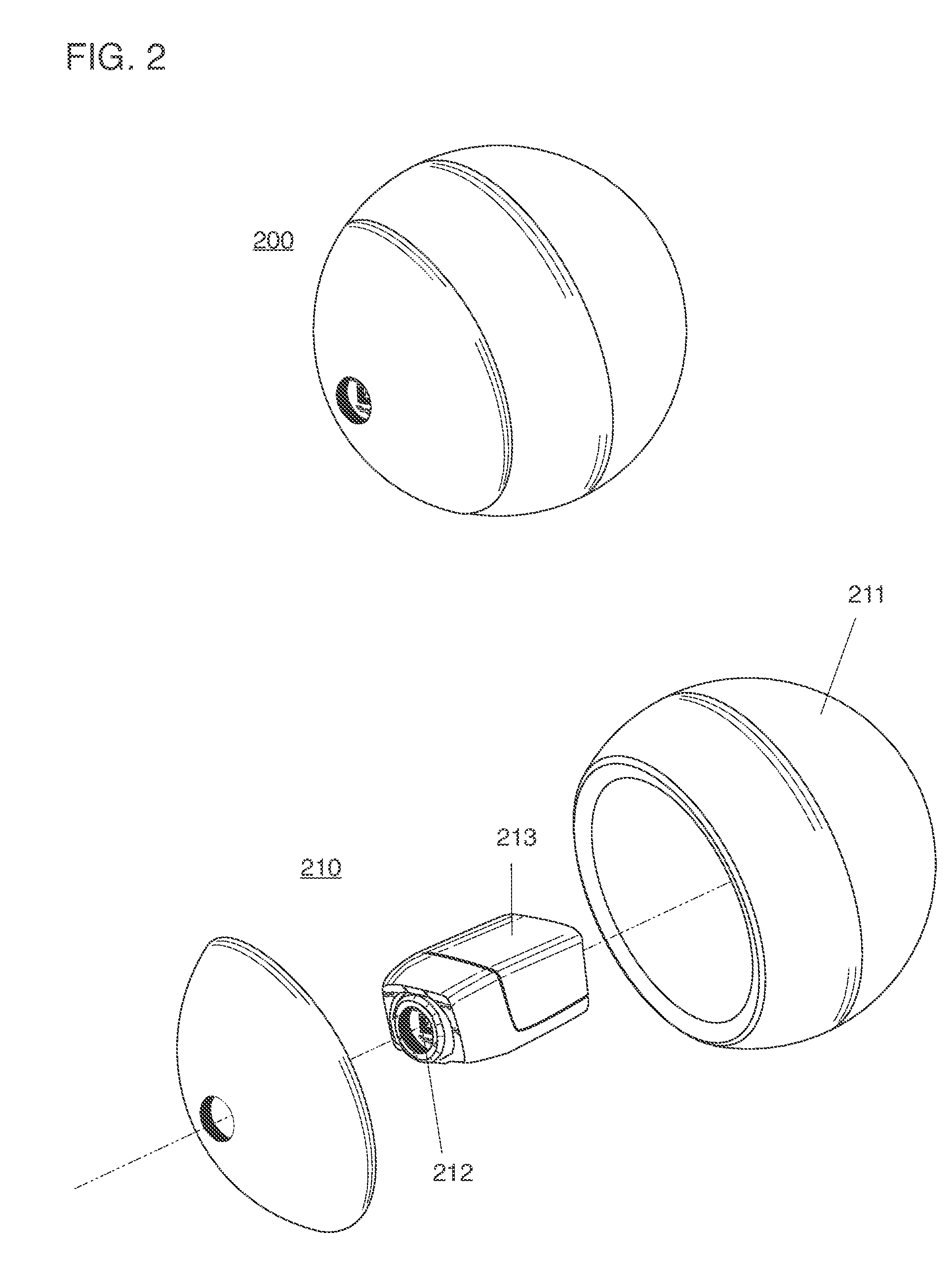
[0087]A ball capable of isolating image capture to a desired subject or perspective and further capable of changing its trajectory in order to improve the capture of video or still images is made possible by the advent of shock-resistant microelectronic GPS sensing packages, gyroscopes and multi-axis accelerometers and the availability of inexpensive high-capacity storage and low-light, high-speed image capture electronics.

[0088]Because the ball of this invention describes the capture of images from the viewpoint of a smooth arc, a video produced by the ball is substantially improved by comparison with conventional means for moving a camera. A movie captured by the ball of this invention would also be easier and faster to produce than one that required the installation of a dolly, a steadicam, a kite, or other unwieldy configuration. Lastly, a movie captured by the ball of this invention would represent a view of environments unavailable to conventional cranes, helicopters or survei...


PUM


Abstract

A ball-shaped camera thrown or projected into an airborne trajectory, and an image capture system with network devices collaborating for the purpose of generating panoramic images and video sourced from network ball cameras, and ball cameras capable of capturing stable image and video while spinning, spiraling or precessing through a trajectory.

Description

CROSS-REFERENCE TO RELATED APPLICATIONS[0001]The present application is a continuation-in-part of U.S. patent application Ser. No. 13 / 492,616, Ball with camera and trajectory control for reconnaissance or recreation, filed Jun. 8, 2012, which is a continuation of U.S. patent application Ser. No. 12 / 772,198, now U.S. Pat. No. 8,237,787, Ball with camera and trajectory control for reconnaissance or recreation, filed May 1, 2010, which claims priority from U.S. Provisional Patent Application 61 / 226,618, Ball with camera and trajectory control for reconnaissance or recreation, filed Jul. 17, 2009, and also, U.S. Provisional Patent Application 61 / 177,769, Recreational Ball with Trainable Camera, filed May 13, 2009, and also, U.S. Provisional Patent Application 61 / 174,994, Recreational Ball, filed May 2, 2009. The entire contents of these applications are incorporated herein by reference.STATEMENT REGARDING FEDERALLY SPONSORED RESEARCH DEVELOPMENT[0002]Not applicable.BACKGROUND OF THE INV...

Claims


Application Information

Patent Timeline
Patent Type & Authority Applications(United States)
IPC IPC(8): A63B43/00
CPCH04N5/2252H04N5/232H04N5/23238H04N5/2258H04N5/2259A63B43/00A63B37/0004H04N23/58H04N23/45H04N23/50H04N23/51H04N23/662H04N23/66H04N23/61H04N23/80H04N23/698H04N7/181H04N23/54H04N23/56H04N23/90H04N23/611A63B2102/32A63B37/0003A63B43/004A63B43/06A63B2209/08A63B2220/806
Inventor HOLLINGER, STEVEN J.
Owner HOLLINGER STEVEN J
Why Eureka
Try Eureka