Methods, Devices, Systems, Circuits and Associated Computer Executable Code for Detecting and Predicting the Position, Orientation and Trajectory of Surgical Tools

a technology of positioning and trajectory, applied in the field of medical imaging, can solve the problems of unintentional change of direction, tool thinness and flexibleness, and difficult to guess the guide trajectory of surgeons,

Inactive Publication Date: 2013-08-15
ORTHOPEDIC NAVIGATION
View PDF10 Cites 531 Cited by
  • Summary
  • Abstract
  • Description
  • Claims
  • Application Information

AI Technical Summary

Benefits of technology

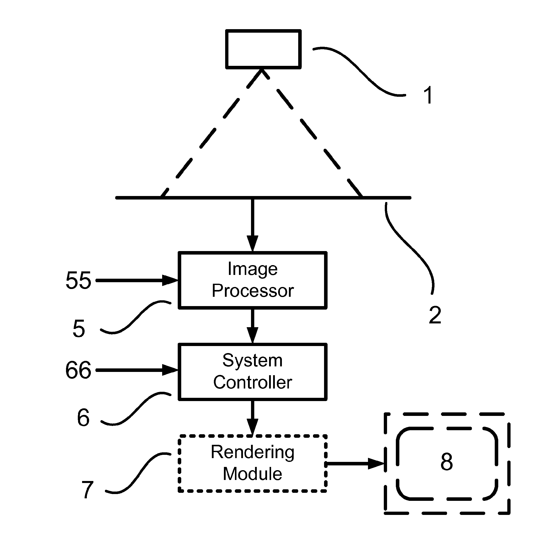
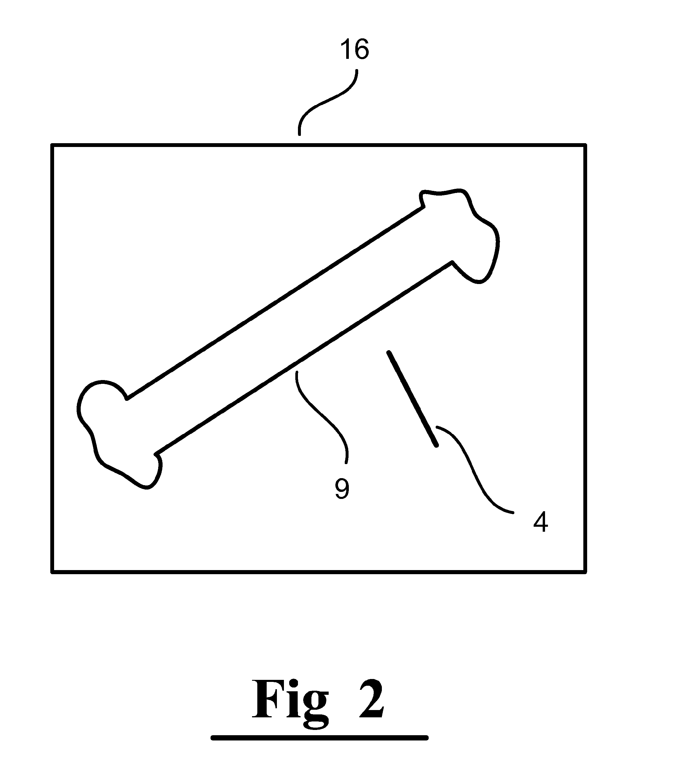
[0012]According to some embodiments of the present invention, the system controller, and / or image processing logic functionally associated therewith, may determine the tool's position by matching the captured image of the tool to a stored image or model (e.g. mathematical model) of the tool (skeleton) digitally stored in a repository of possible tool images or other tool related parameters. According to some embodiments of the present invention, the system controller may detect and possibly determine an extent of tool bending by identifying variation in expected spatial relationships between points on the tool. According to some embodiments of the present invention, the system controller may predict the expected trajectory of the tool by extrapolating a deflection path of the tool.

Problems solved by technology

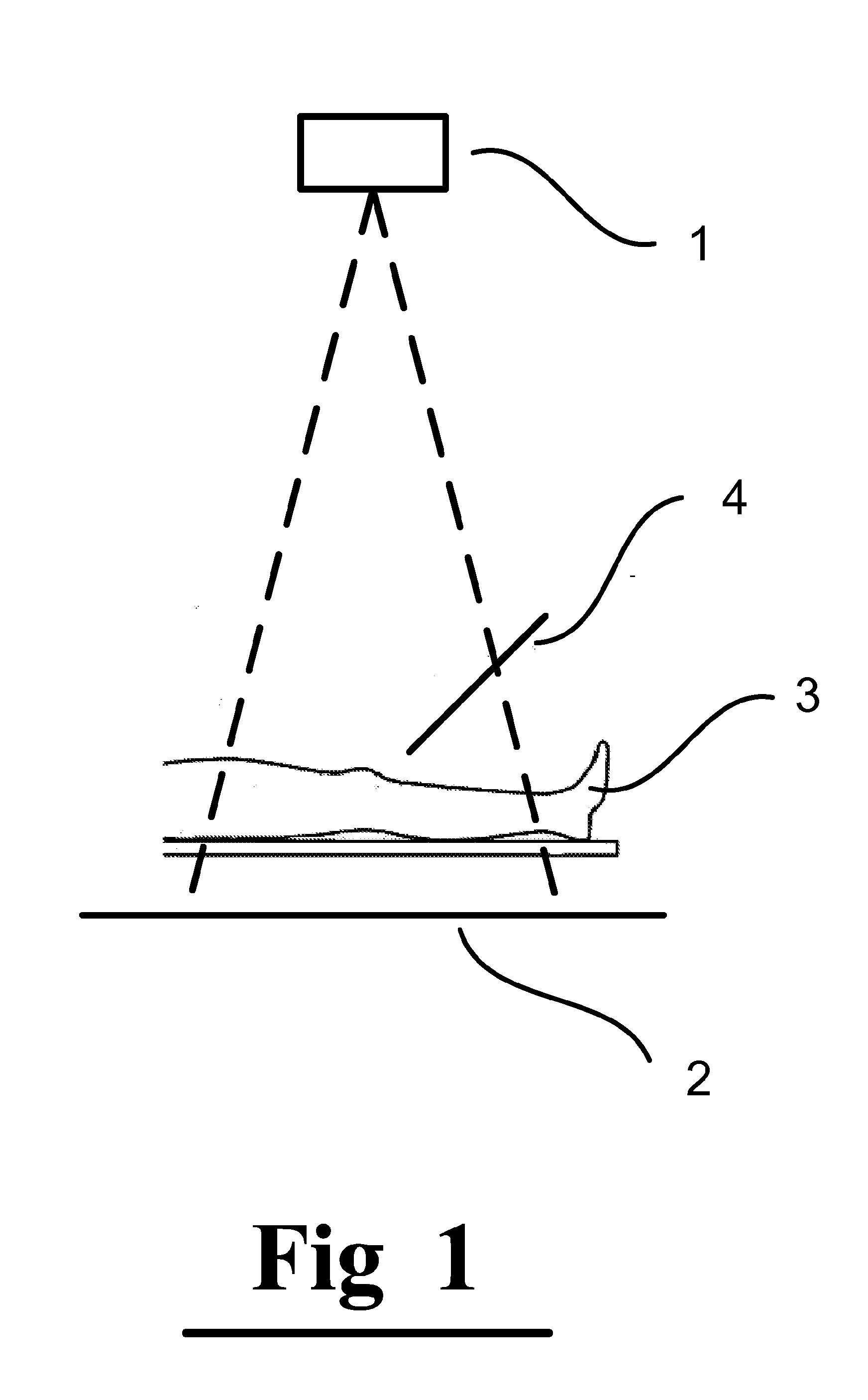
In many cases the tools are very thin and flexible and may bend or be otherwise distorted during an operation.
When the tool bends it may take a curved path which is initially unnoticeable by the surgeon but may eventually end up at a place other than its intended target position.
Sometimes guides bend by accident, when a guide is deflected off a more rigid part of the bone and takes on a curved path, or when the surgeon, unintentionally changes the direction in which he holds the power drill while drilling.
One of the problems caused by bent guides is that surgeons have a hard time guessing the guide trajectory.

Method used


Image

  • Methods, Devices, Systems, Circuits and Associated Computer Executable Code for Detecting and Predicting the Position, Orientation and Trajectory of Surgical Tools
  • Methods, Devices, Systems, Circuits and Associated Computer Executable Code for Detecting and Predicting the Position, Orientation and Trajectory of Surgical Tools
  • Methods, Devices, Systems, Circuits and Associated Computer Executable Code for Detecting and Predicting the Position, Orientation and Trajectory of Surgical Tools

Examples


Embodiment Construction

[0032]In the following detailed description, numerous specific details are set forth in order to provide a thorough understanding of the invention. However, it will be understood by those skilled in the art that the present invention may be practiced without these specific details. In other instances, well-known methods, procedures, components, circuits and algorithms have not been described in detail so as not to obscure the present invention.

[0033]Unless specifically stated otherwise, as apparent from the following discussions, it is appreciated that throughout the specification discussions utilizing terms such as “processing”, “computing”, “calculating”, “determining”, or the like, refer to the action and / or processes of a computer or computing system, or similar electronic computing device, that manipulate and / or transform data represented as physical, such as electronic, quantities within the computing system's registers and / or memories into other data similarly represented as ...


PUM


Abstract

The present invention includes methods, devices, systems, circuits and associated computer executable code for detecting and predicting the position and trajectory of surgical tools. According to some embodiments of the present invention, images of a surgical tool within or in proximity to a patient may be captured by a radiographic imaging system. The images may be processed by associated processing circuitry to determine and predict position, orientation and trajectory of the tool based on 3D models of the tool, geometric calculations and mathematical models describing the movement and deformation of surgical tools within a patient body.

Description

PRIORITY CLAIM[0001]The present application claims priority from Provisional Patent Application No. 61 / 590,432, titled: “A Method Device and System for Detecting the Position and Trajectory of Surgical Tools”, filed by the inventor of the present application on Jan. 25, 2012.FIELD OF THE INVENTION[0002]The present invention relates generally to the field of medical imaging. More specifically, the present invention relates to methods, devices, systems, circuits and associated computer executable code for detecting and predicting the position, orientation and trajectory of surgical tools.BACKGROUND[0003]In modern surgery, a plethora of invasive tools are used regularly to facilitate a wide variety of procedures within the human body. Such tools include drills, needles, guides, lasers, blades and many more. These tools are being used, among other things, for reaching the target positioning of implants, for fixating an anatomical element during trauma surgeries, for acting as a lead for...

Claims


Application Information

Patent Timeline
Patent Type & Authority Applications(United States)
IPC IPC(8): A61B5/00A61B5/06A61B5/055A61B6/00A61B6/03
CPCA61B19/00G06T2207/30021A61B6/485A61B6/463A61B6/032A61B6/52A61B5/7264A61B5/064A61B5/062A61B5/743G06T7/0046A61B19/5244A61B2019/507A61B2019/5265A61B2019/5466G06T2207/10072G06T2207/10116A61B5/055A61B34/20A61B2034/107A61B2034/2065A61B2090/3966G06T7/75
Inventor NATHANIEL, RAM
Owner ORTHOPEDIC NAVIGATION
Why Eureka
Try Eureka