Apparatus for cutting and aspirating tissue

a tissue suctioning and apparatus technology, applied in the field of apparatus for cutting and aspirating tissue, can solve the problems of difficult work speed [with the instrument] because of the frequency with which the inner tube is inserted, and the known device generates very significant pressure and/or vacuum fluctuations in the ey

Active Publication Date: 2013-08-15
GEUDER VOLKER
View PDF2 Cites 12 Cited by
  • Summary
  • Abstract
  • Description
  • Claims
  • Application Information

AI Technical Summary

Benefits of technology

[0023]As already mentioned above, the outer tube has inner cutting edges, and the inner tube has outer cutting edges, wherein the cutting edges of each slide past each other when the inner tube executes a stroke, thereby producing the cutting effect both upon the forward stroke and the backward stroke. Defined cutting surfaces extend from the cutting edges as a result of the material thickness of the tubes, and specifically in each case falling away outward from the cutting edge (in the case of the outer tube) and / or inward (in the case of the inner tube). As such, it is possible to define each cutting edge via the cutting surface, and also optionally sharpen and / or machine finish the same.

Problems solved by technology

However, the known devices of the type which characterizes the class are problematic in practice for two reasons.
First, the work speed [with the instrument] is limited by the frequency with which the inner tube is moved back and forth, particularly with its outer cutting edge moving past the inner—or the inner cutting edge moving past the outer—tube.
In addition, it is disadvantageous that the known device generates very significant pressure and / or vacuum fluctuations in the eye, particularly as a result of the fact that the opening or openings which serve to provide suctioning is / are alternatingly completely closed and completely open according to the position of the inner tube.
As a result, an alternating vacuum is created in the body and / or eye which is essentially impossible to compensate.
The resulting significant pressure fluctuations can lead to damage to the eye.

Method used


Image

  • Apparatus for cutting and aspirating tissue
  • Apparatus for cutting and aspirating tissue
  • Apparatus for cutting and aspirating tissue

Examples


Embodiment Construction

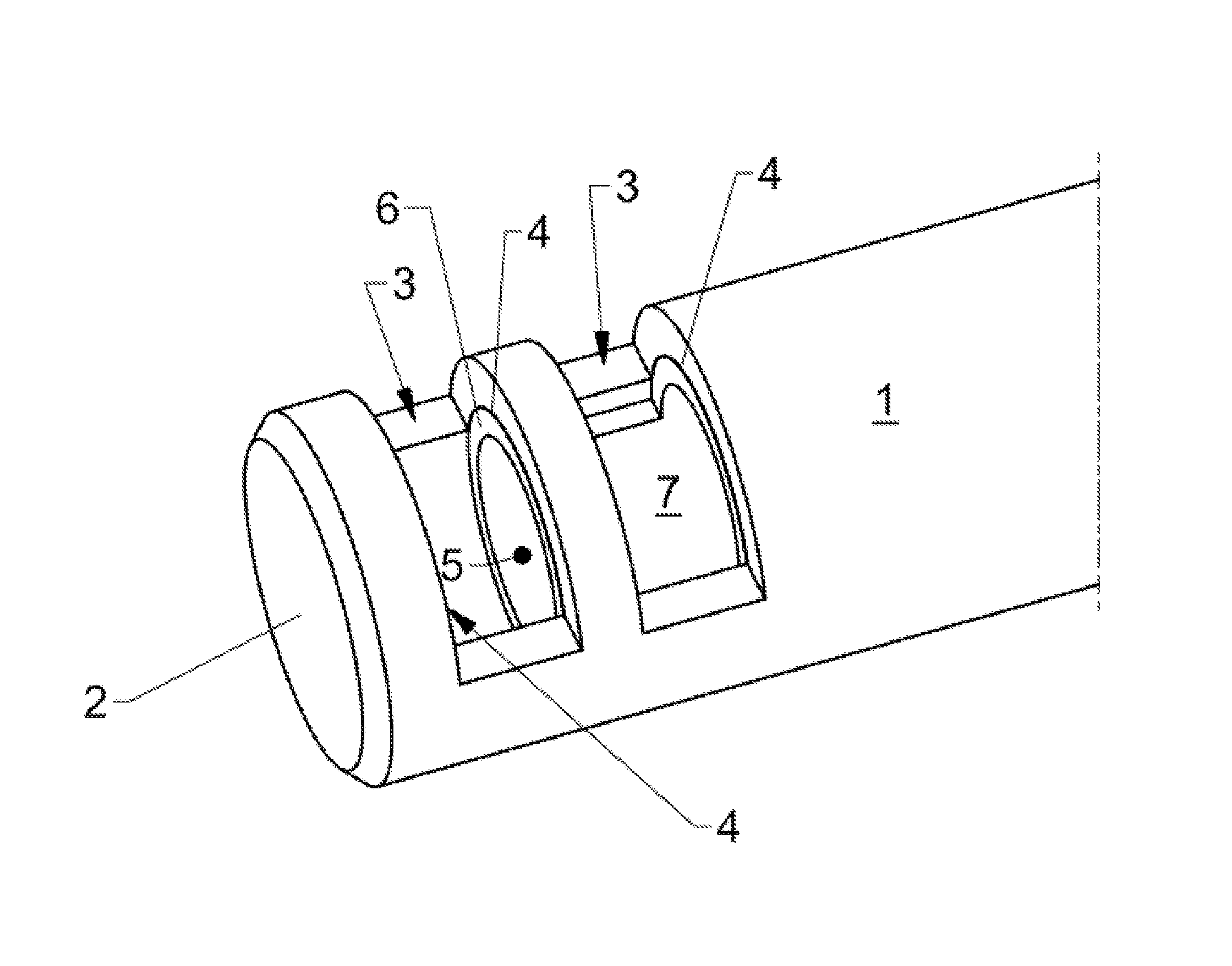
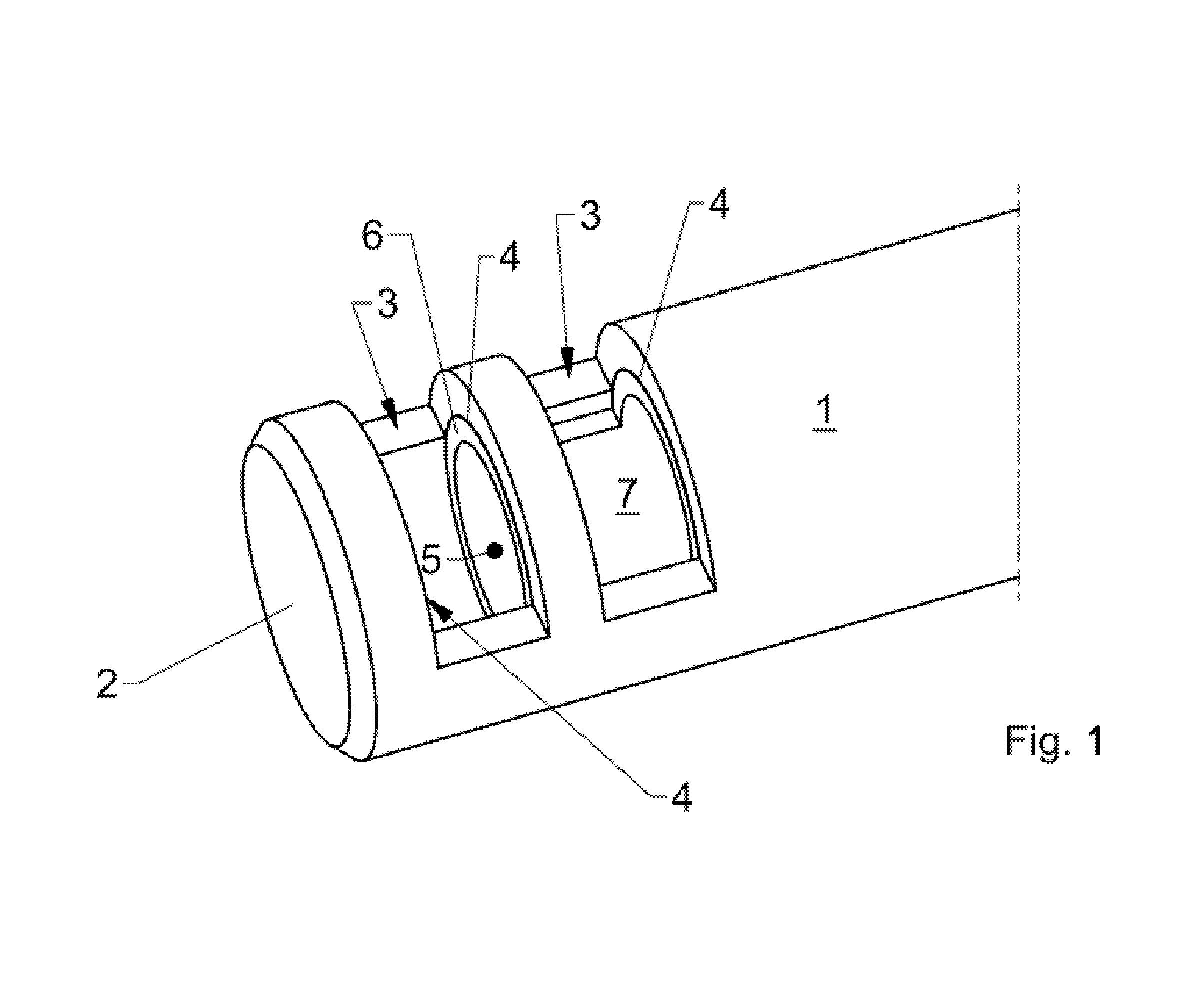
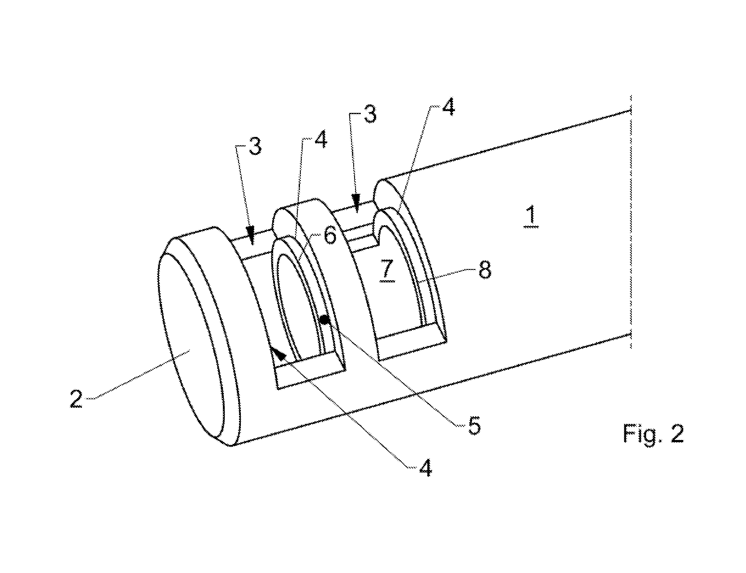
[0029]FIGS. 1 to 6 show highly enlarged schematic views of the working region of the device according to the invention, wherein the same is a so-called vitrector for application in vitrectomies, particularly a device for the removal of vitreous humor from the human eye.

[0030]Together, FIGS. 1 to 6 show the movement profile and the positions of the moving parts relative to each other.

[0031]More concretely, FIGS. 1 to 6 partially show the outer tube 1 which is closed on the free end 2. In the embodiment shown in FIGS. 1 to 6, the outer tube 1 is equipped with a total of two openings 3 which are designed in the shape of symmetrical slits. Due to the disposition of the two openings 3, the outer tube 1 has a total of four cutting edges 4.

[0032]An inner tube 5 is arranged concentrically inside of the outer tube 1, with minimal play, and is able to slide back and forth. It is possible to see in FIGS. 1 to 6 that the inner tube 5 is open on its frontal free end. Accordingly, a first cutting...


PUM


Abstract

An apparatus for cutting and aspirating tissue from the human body or animal body, particularly for application in vitrectomies, for retinal detachment, etc., having an outer tube (1) and an inner tube (5) which can slide back and forth concentrically in the outer tube (1) with minimal play, wherein the outer tube (1) is closed on the free end (2) thereof, and has a lateral opening (3) near the free end (2), with at least one inner cutting edge (4), wherein the inner tube (5) is open on the free end and has an outer cutting edge (6) at that position, and wherein the cutting edges (4, 6) work together in a cutting manner when the inner tube (5) is displaced, characterized in that the inner tube (5) has at least one lateral opening (7) with at least one further outer cutting edge (8) near the free end.

Description

CROSS REFERENCE TO RELATED APPLICATIONS[0001]This application is a national stage application, filed under 35 U.S.C. §371, of International Application No. PCT / DE2011 / 050043, filed Oct. 11, 2011, which claims priority to and the benefit of German Application No. 10 2010 050 337.1, filed Nov. 5, 2010, the contents of both of which are hereby incorporated by reference in their entirety.BACKGROUND[0002]1. Technical Field[0003]The invention relates to a device for the cutting and suctioning of tissue from the human body or animal body, particularly for application in vitrectomies, in cases of retinal detachment, etc. The device includes an outer tube and an inner tube which can slide concentrically inside the outer tube in both directions with minimal play, wherein the outer tube is closed on the free end thereof, and has a lateral opening with at least one inner cutting edge near the free end. The inner tube is open on the free end and has an outer cutting edge at this position. The cu...

Claims


Application Information

Patent Timeline
Patent Type & Authority Applications(United States)
IPC IPC(8): A61F9/007
CPCA61B10/0275A61B17/32002A61F9/00763A61B2217/005A61B2017/320028
Inventor GEUDER, VOLKER
Owner GEUDER VOLKER
Why Eureka
Try Eureka