Reference clock re-timing scheme in electronic circuits

a reference clock and electronic circuit technology, applied in the field of reference clock retiming scheme for use in electronic circuits, can solve problems such as wrong count value reading and metastability issues

Active Publication Date: 2013-08-15
TEXAS INSTR INC
View PDF4 Cites 28 Cited by
  • Summary
  • Abstract
  • Description
  • Claims
  • Application Information

AI Technical Summary

Benefits of technology

[0009]A phase locked loop (PLL) generates an error signal representing a phase difference between a reference clock and an output clock. Each of an integer portion and a fractional portion of a number of complete cycles of the output clock occurring at each active edge of the reference clock is determined. A magnitude of the fractional portion is compared with each of a first threshold and a second threshold, the first threshold representing a first fraction of one cycle of the output clock and the second threshold representing a second fraction of one cycle of the output clock. A first re-timed clock is selected to obtain the integer portion if the magnitude of the fractional portion is either less than or equal to the first threshold or greater than or equal to the second threshold. A second re-timed clock is selected to obtain the integer portion if the magnitude of the fractional portion is greater than the first threshold and less than the second threshold.
[0010]A phase detector for generating an error signal representing a phase difference between a reference clock and an output clock includes a counter, a fractional count determination circuit, and a pair of summing blocks. The counter is designed to generate a

Problems solved by technology

Therefore, the counter may be updating its count value when being read at a clock edge of the reference clock, thereby potentially resulting in a

Method used


Image

  • Reference clock re-timing scheme in electronic circuits
  • Reference clock re-timing scheme in electronic circuits
  • Reference clock re-timing scheme in electronic circuits

Examples


Embodiment Construction

[0028]Various embodiments are described below with several examples for illustration.

[0029]1. Example Component

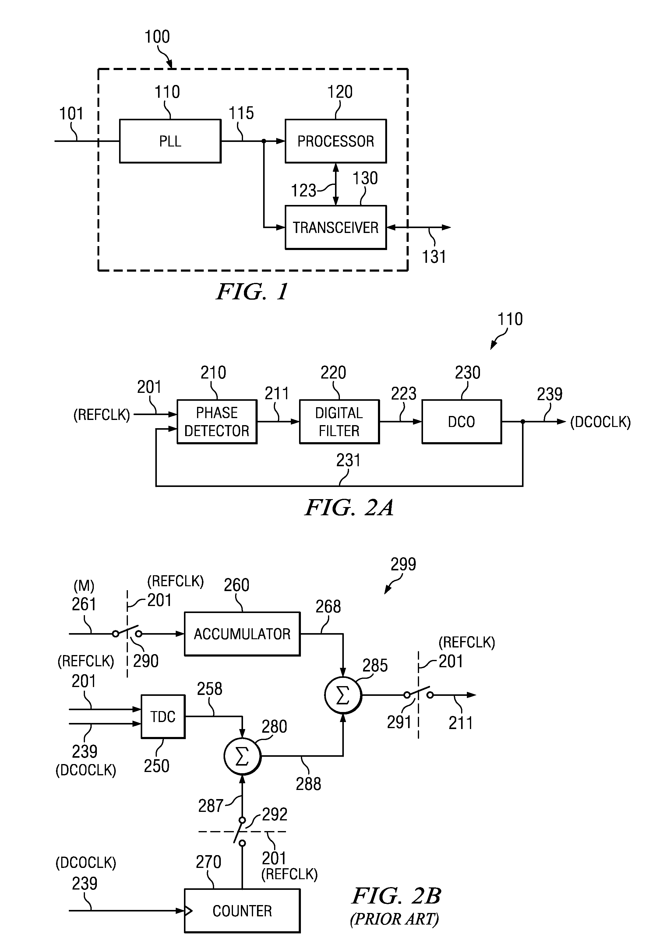
[0030]FIG. 1 is a block diagram of an example component in which several embodiments of the present disclosure can be implemented. The diagram shows integrated circuit (IC) 100 containing phase locked loop (PLL) 110, processor 120 and transceiver 130. The specific blocks of IC100 are shown merely by way of illustration, and typical implementations of IC 100 may contain more or fewer blocks.

[0031]Processor 120 receives a clock on path 115. The operations of processor 120 may be synchronized with respect to clock 115. Processor 120 may generate data to be processed by transceiver 130, and provide the data to transceiver 130 on path 123. Processor 120 may receive data from transceiver 130 also on path 123. In general, processor 120 operates to provide various features designed to be provided by a system or device containing IC 100. When implemented in a wireless communications...


PUM


Abstract

A phase detector includes a counter to generate the integer portion of a number of complete cycles of an output clock at each active edge of a reference clock. A time to digital converter in the phase detector generates the fractional portion of the number of complete cycles of the output clock at each active edge of the reference clock. The sum of the fractional portion and the integer portion is subtracted from an accumulated value obtained by accumulating a pre-determined number to generate an error signal as the output of the phase detector. The counter is read at an active edge of one of two re-timed clocks derived from the reference clock. Each of the two re-timed clocks is generated based on a comparison of the fractional portion with a pair of thresholds. Errors due to metastability in reading the counter are thereby avoided.

Description

BACKGROUND[0001]1. Technical Field[0002]Embodiments of the present disclosure relate generally to electronic circuits, and more specifically to a method of reference clock re-timing scheme for use in electronic circuits.[0003]2. Related Art[0004]There are several electronic circuits or components in which a reference clock is used to perform an operation such as, for example, reading the contents of a register. Phase detectors and time-to-digital-converter-based analog to digital converters (ADC) are some examples of such electronic circuits.[0005]Phase detectors are commonly used in phase locked loop (PLL) circuits to generate an error signal representing a phase difference between a reference clock and an output clock of the PLL. In one phase detector implementation, a digital phase detector (PD) generates the phase error by computing a difference between a reference phase and an estimated phase. The reference phase is represented by a pre-determined number that equals the number ...

Claims


Application Information

Patent Timeline
IPC IPC(8): G06F19/00
CPCH03L7/08H03L2207/50H03L7/091
Inventor PRATHAPAN, INDUNAGARAJ, KRISHNASAWAMYZHANG, FRANK
Owner TEXAS INSTR INC
Why Eureka
Try Eureka