Induced draught fan

a technology of draught fan and draught plate, which is applied in the direction of machines/engines, mechanical equipment, liquid fuel engines, etc., can solve the problems of increased production cost and disadvantageous quality control, and achieves simple structure, good sealing effect, and easy installation procedures

Active Publication Date: 2013-08-22
ZHONGSHAN BROAD OCEAN
View PDF10 Cites 10 Cited by
  • Summary
  • Abstract
  • Description
  • Claims
  • Application Information

AI Technical Summary

Benefits of technology

[0007]In view of the above-described problems, it is one objective of the invention to provide an induced draught fan which has advantages of a simple structure, easy installation procedures and a good seal effect in keeping foreign matters such as dust from entering into the inside of the volute and keeping the normal operation of the wind wheel.

Problems solved by technology

It greatly increases production cost and is disadvantageous for the quality control.

Method used


Image

  • Induced draught fan
  • Induced draught fan
  • Induced draught fan

Examples


example 1

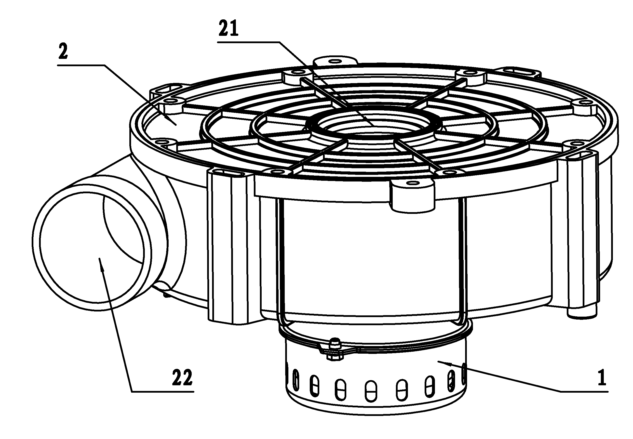
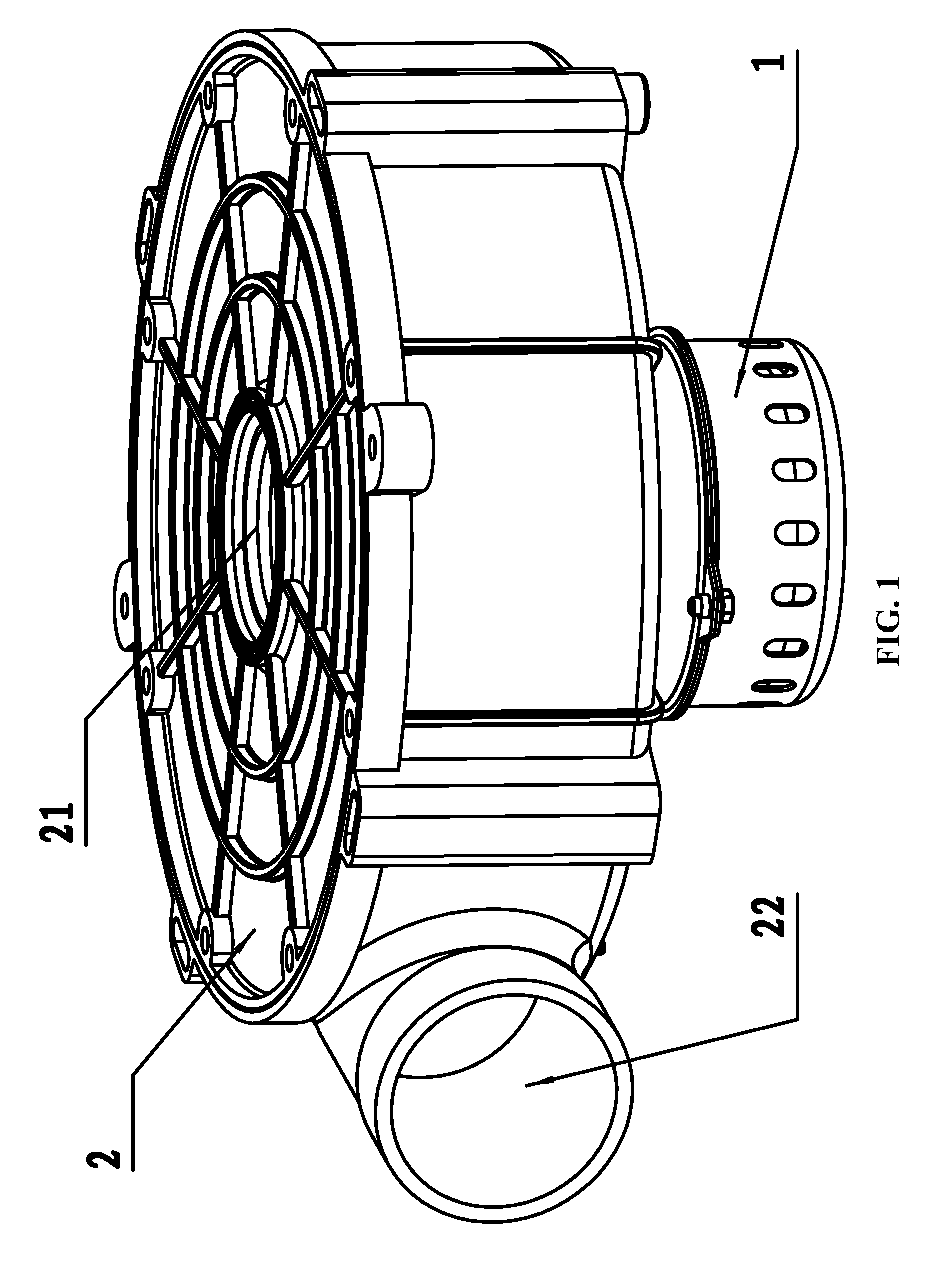
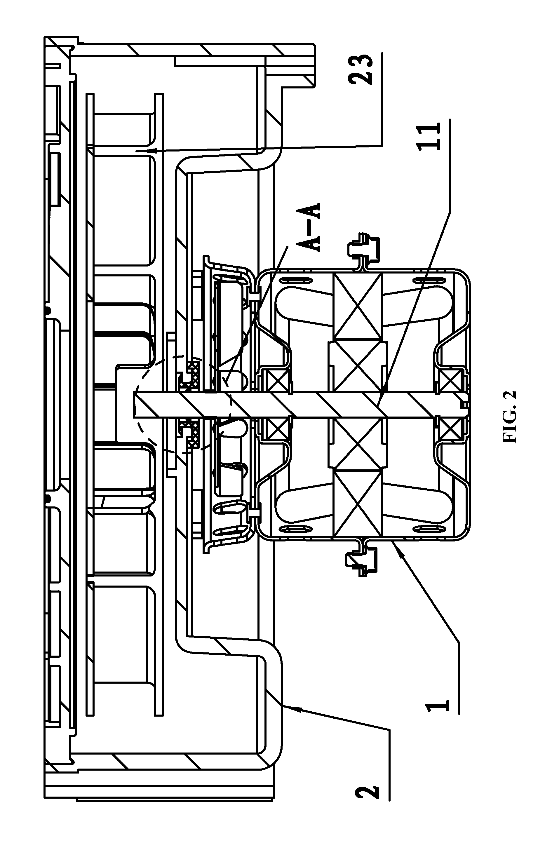
[0041]As shown in FIGS. 1-4, an induced draught fan comprises a motor 1, a volute 2, and a wind wheel 23. The volute 2 is provided with an air intake 21 and an air outlet 22. The wind wheel 23 is arranged inside the volute 2. The top of the volute 2 is provided with a through-hole 24. The shaft 11 of the motor 1 passes through the through-hole 24 and is connected with the wind wheel 23. A seal ring 3 is arranged on the volute 2 corresponding to the through-hole 24. The outer side of the seal ring 3 is provided with an annular groove 31. The volute 2 is embedded in the annular groove 31. The middle of the seal ring 3 is provided with a center hole 32. The middle of the side wall of the center hole 32 is provided with a ring-like convex edge 33. The shaft 11 passes through the center hole 32 and contacts with the ring-like convex edge 33. The inner wall of the through-hole 24 is provided with a ring-like convex boss 25a. The ring-like convex boss 25a is embedded in the annular groove ...

example 2

[0042]As shown in FIG. 1, FIG. 5, FIG. 6, FIG. 7, and FIG. 8, an induced draught fan comprises a motor 1, a volute 2, and a wind wheel 23. The volute 2 is provided with an air intake 21 and an air outlet 22. The wind wheel 23 is arranged inside the volute 2. The top of the volute 2 is provided with a through-hole 24. The shaft 11 of the motor 1 passes through the through-hole 24 and is connected with the wind wheel 23. The seal ring 3 is arranged on the volute 2 corresponding to the through-hole 24. The outer side of the seal ring 3 is provided with an annular groove 31. The volute 2 is embedded in the annular groove 31. The middle of the seal ring 3 is provided with a center hole 32. The middle of the side wall of the center hole 32 is provided with a ring-like convex edge 33. The shaft 11 passes through the center hole 32 and contacts with the ring-like convex edge 33. The top of the volute 2 protrudes outward to form an annular edge 26 at the edge of the through-hole 24. The inne...

example 3

[0044]As shown in FIG. 9, FIG. 10, FIG. 11, FIG. 12 and FIG. 13, the volute 2 is provided with a manometric interface 4. A cavity 27 for receiving the wind wheel is provided in the middle of the volute. The volute 2 is provided with a first through-hole 28. A second through-hole 41 is positioned in the middle of the manometric interface 4 which is arranged on the volute 2. The second through-hole 41 and the cavity 27 communicate. The end face of the manometric interface 4 protrudes to form a spoiler block 42 which is positioned in the cavity 27 and is capable of rotating with the manometric interface 24 in circumferential direction along the first through-hole 28. A seal cover 5 is provided at the first through-hole 28 outside the manometric interface 4. The seal cover 5 comprises a body 51 comprising an installation hole 52 in the middle. The slot 53 is provided on the body 51 outside the installation hole 52. The slot 53 is embedded in the base board of the volute 2. The manometri...


PUM


Abstract

An induced draught fan, including: a motor, the motor including a shaft; a volute; and a wind wheel. The volute is provided with an air intake and an air outlet. The wind wheel is arranged inside the volute. The top of the volute is provided with a through-hole. The shaft of the motor passes through the through-hole and is connected to the wind wheel. A seal ring is arranged on the volute corresponding to the through-hole. An outer side of the seal ring is provided with an annular groove. The volute is embedded in the annular groove. The middle of the seal ring is provided with a center hole. The middle of the side wall of the center hole is provided with a ring-like convex edge. The shaft passes through the center hole and contacts with the ring-like convex edge.

Description

CROSS-REFERENCE TO RELATED APPLICATIONS[0001]This application is a continuation-in-part of International Patent Application No. PCT / CN2012 / 074793 with an international filing date of Apr. 27, 2012, designating the United States, now pending, and further claims priority benefits to Chinese Patent Application No. 201120497688.0 filed Dec. 3, 2011. The contents of all of the aforementioned applications, including any intervening amendments thereto, are incorporated herein by reference. Inquiries from the public to applicants or assignees concerning this document or the related applications should be directed to: Matthias Scholl P.C., Attn.: Dr. Matthias Scholl Esq., 14781 Memorial Drive, Suite 1319, Houston, Tex. 77079.BACKGROUND OF THE INVENTION[0002]1. Field of the Invention[0003]The invention relates to an induced draught fan.[0004]2. Description of the Related Art[0005]A traditional induced draught fan includes a motor, a volute, and a wind wheel. The top of the volute is provided ...

Claims


Application Information

Patent Timeline
Patent Type & Authority Applications(United States)
IPC IPC(8): F04D29/10
CPCF04D29/102F04D29/122F04D29/4226
Inventor WANG, XIONGCHENGLEI, WEI
Owner ZHONGSHAN BROAD OCEAN
Why Eureka
Try Eureka