Pi-shaped preform with bias fibers

a fiber and bias technology, applied in the field of woven preforms, can solve the problems of introducing differences in the thermal expansion coefficient, the inability to use metal bolts or rivets at the interface of such components, and the “peel” for

Active Publication Date: 2013-08-22
ALBANY ENGINEERED COMPOSITES
View PDF5 Cites 23 Cited by
  • Summary
  • Abstract
  • Description
  • Claims
  • Application Information

AI Technical Summary

Benefits of technology

[0019]Accordingly, an object of the present invention is to provide a woven preform th...

Problems solved by technology

Typically, however, they will not be of the same materials or have comparable physical, chemical thermal or other properties, since a usual objective sought in using composites in the first place is to achieve a combination of characteristics in the finished product that is not attainable through the use of one constituent material alone.
However, when tension is applied to the cured panel or the skin of the composite structure, loads at unacceptably low values resulted in “peel” forces which separate the stiffening element from the panel at their interface since the effective strength of the joint is that of the adhesive and not of the matrix material.
The use of metal bolts or rivets at the interface of such components is unacceptable because such additions at least partially destroy and weaken the int...

Method used


Image

  • Pi-shaped preform with bias fibers
  • Pi-shaped preform with bias fibers
  • Pi-shaped preform with bias fibers

Examples


Embodiment Construction

[0038]The terms “fibers” and “yarns” are interchangeably used in the following description. However, “fibers” and “yarns” as used herein can refer to monofilaments, multifilament yarns, twisted yarns, multifilament tows, textured yarns, braided tows, coated yarns, bicomponent monofilament yarns, as well as yarns made from stretch broken fibers.

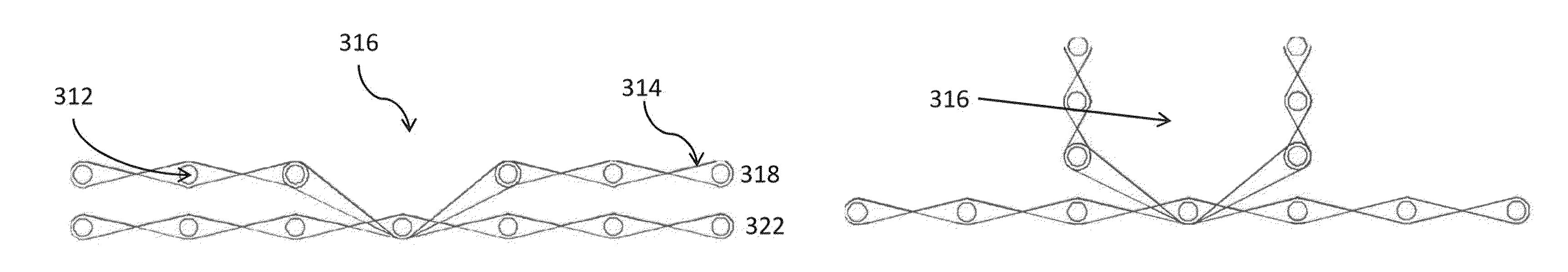
[0039]Turning now to FIG. 4, the Pi preform 300 according to the present invention can be woven on any conventional weaving machine 215. FIG. 4, for example, is a top view of a weaving machine 215 with the preform 300 still on the machine in an “as-woven” form before the woven fabric is taken off the loom. The vertical lines in fabric 300 represent warp fibers or yarns 312, and the horizontal lines represent weft fibers or yarns 314. While carbon fiber is preferred, the warp and / or weft fibers can practically be any other fiber type, such as for example, glass, ceramic, aramid, polyethylene, polypropylene etc, or a combination thereof.

[0040]...


PUM

PropertyMeasurementUnit
Angleaaaaaaaaaa
Lengthaaaaaaaaaa
Widthaaaaaaaaaa

Abstract

A woven preform for a reinforced composite material, which may be woven flat and folded into shape. The preform has off-axis reinforcement with one or more legs and/or base extending in an off axis or bias (non 0/90 degree) orientation with respect to the warp/weft fibers. One or more legs extend from a base, the base and legs each having at least two layers of warp fibers. The legs may be parallel or angled to each other. The outer ends of the base and/or the legs may have tapers formed from terminating layers of warp fibers in a stepped or angled pattern.

Description

BACKGROUND OF THE INVENTION[0001]1. Field of the Invention[0002]This invention generally relates to woven preforms and particularly relates to woven preforms used in reinforced composite materials, which can be woven flat and folded into its final shape.[0003]2. Incorporation by Reference[0004]All patents, patent applications, documents, references, manufacturer's instructions, descriptions, product specifications, and product sheets for any products mentioned herein are incorporated herein by reference, and may be employed in the practice of the invention.[0005]3. Description of the Prior Art[0006]The use of reinforced composite materials to produce structural components is now widespread, particularly in applications where their desirable characteristics are sought of being light in weight, strong, tough, thermally resistant, self-supporting and adaptable to being formed and shaped. Such components are used, for example, in aeronautical, aerospace, satellite, recreational (as in r...

Claims


Application Information

Patent Timeline
IPC IPC(8): D03D3/00B31B1/26D06H7/00D03D1/00D03D11/00
CPCB29B11/16B29C70/24D03D1/00Y10T428/2419D10B2101/12D10B2505/02D03D11/02D03D25/005Y10T442/3203
Inventor GILBERTSON, BROCKGOERING, JONATHAN
Owner ALBANY ENGINEERED COMPOSITES
Why Eureka
Try Eureka