
Pneumatic tire

a technology of pneumatic tires and tires, applied in the field of pneumatic tires, can solve problems such as comfort and stability reduction, and achieve the effect of balancing tire wear life and resistance to uneven tire wear

Active Publication Date: 2013-08-29
BRIDGESTONE CORP
View PDF11 Cites 3 Cited by
  • Summary
  • Abstract
  • Description
  • Claims
  • Application Information

AI Technical Summary

Benefits of technology

The patent text aims to address the problem of tire wear caused by uneven forces on the tire. The invention aims to provide a pneumatic tire that is more resistant to uneven wear without changing the shape of the crown portion. The technical effect is the enhancement of the tire's resistance to uneven wear to improve its performance characteristics such as comfort and stability.

Problems solved by technology

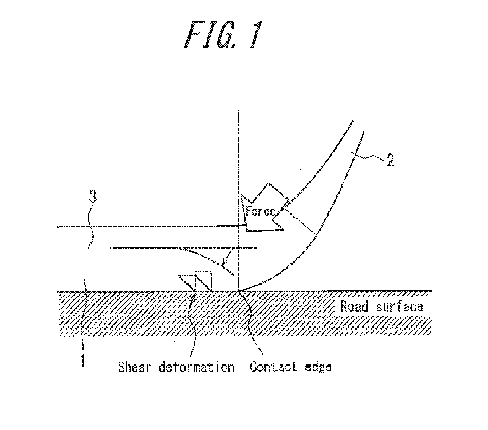
However, decreasing the difference in radius by changing the shape of the crown portion, as in the invention disclosed in Patent Literature 1, also increases the contact length of the shoulder portions, leading to the problem of a reduction in performance characteristics such as comfort and stability.

Method used


Image

  • Pneumatic tire
  • Pneumatic tire
  • Pneumatic tire

Examples


examples

[0089]To verify the effects of the present invention, samples of tires according to the present invention and of tires serving as comparative examples were produced, and tests were performed to assess the resistance to uneven wear and the wear life of the tires.

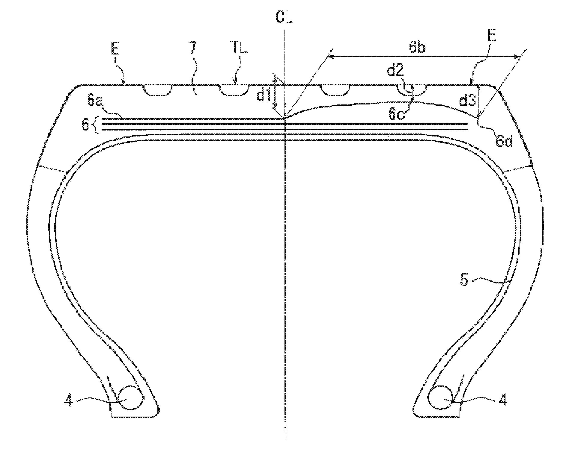
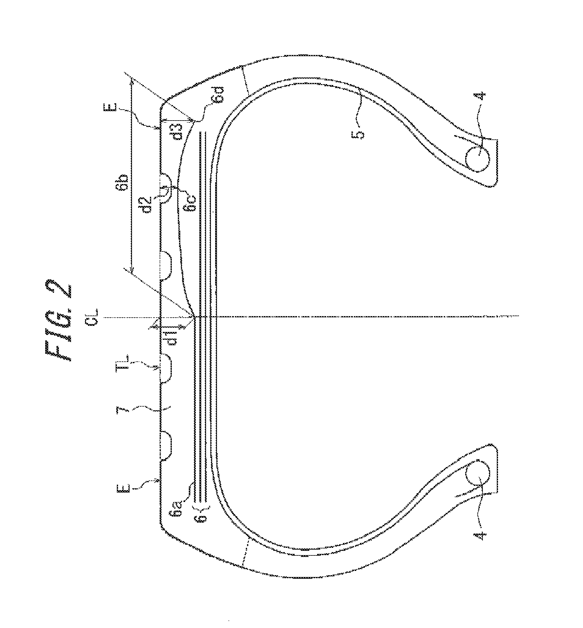
[0090]First, as Inventive Examples 1 and 2, tires were produced with a structure such that, as illustrated in FIGS. 2 and 3, one half, in the tire width direction, of the outermost belt layer curves convexly outward in the radial direction, with a top at a position inwards in the width direction from the contact edge E by 20% of the tread width, and extends inward in the radial direction from the top to the outer edge in the width direction of the outermost belt layer.

[0091]In the tire of Inventive Example 1, the distance between the tread outer contour line and the outermost belt layer decreases gradually along the tire width direction from the tire equatorial plane CL to the top position, whereas the tire of Inventive Examp...


PUM


Abstract

In a tire according to the present invention, the shape of the outermost reinforcing layer in the tire radial direction is optimized.

Description

TECHNICAL FIELD[0001]The present invention relates to a pneumatic tire, and in particular to a pneumatic tire for passenger cars that enhances resistance to uneven wear.BACKGROUND ART[0002]In general, pneumatic tires have a structure such that the crown portion is curved, with the radius of the tread portion growing smaller from the center region towards the shoulder portions.[0003]Due to this difference in radius in the tire width direction, a difference in rolling speed occurs in the tire width direction when the tire is rolling. In particular, the difference in rolling speed becomes pronounced between the center region and the shoulder portions, and the circumferential shear force becomes uneven in the tire width direction.[0004]In particular, a large shear force is generated in the braking direction at the shoulder portions. Due to this shear force, wear progresses in the tread rubber at the shoulder portions, leading to local wear, i.e. uneven wear.[0005]Moreover, when a load i...

Claims


Application Information

Patent Timeline
IPC IPC(8): B60C5/00
CPCB60C9/2006B60C2200/06Y10T152/10495B60C2011/0033B60C2200/04B60C5/00B60C9/28B60C9/30B60C9/22
Inventor KURATA, TAKAYUKI
Owner BRIDGESTONE CORP
Learn More