Alignment Stable Adjustable Antenna Mount

a technology of adjustable antenna mount and aligning stable, which is applied in the direction of fishing, machine supports, manufacturing tools, etc., and can solve problems such as significant expens

Active Publication Date: 2013-08-29
COMMSCOPE TECH LLC
View PDF9 Cites 29 Cited by
  • Summary
  • Abstract
  • Description
  • Claims
  • Application Information

AI Technical Summary

Problems solved by technology

Should the antenna mount lose the desired boresight alignment, for example due to transient wind and/or ice loads, a signif

Method used


Image

  • Alignment Stable Adjustable Antenna Mount
  • Alignment Stable Adjustable Antenna Mount
  • Alignment Stable Adjustable Antenna Mount

Examples


Embodiment Construction

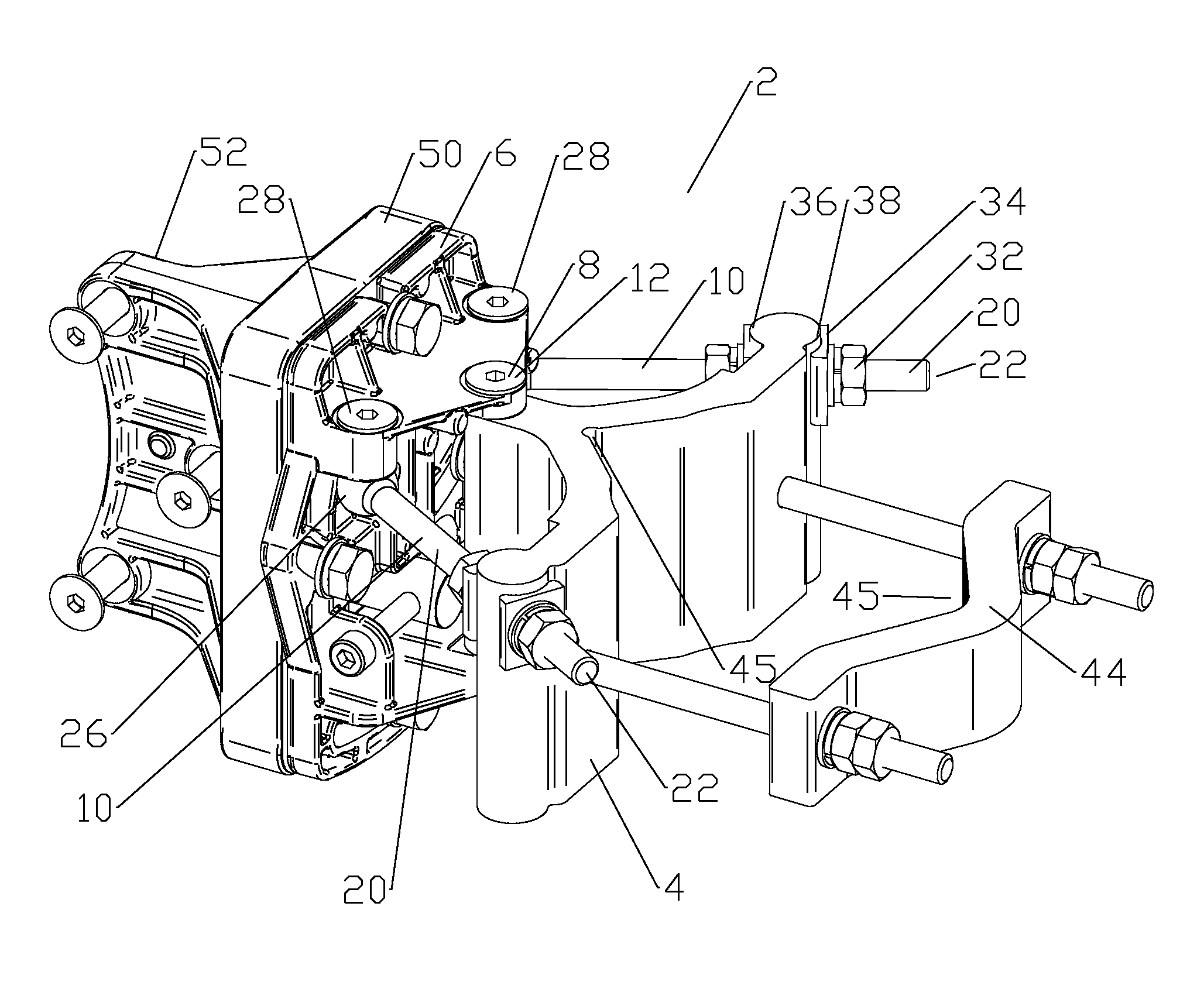
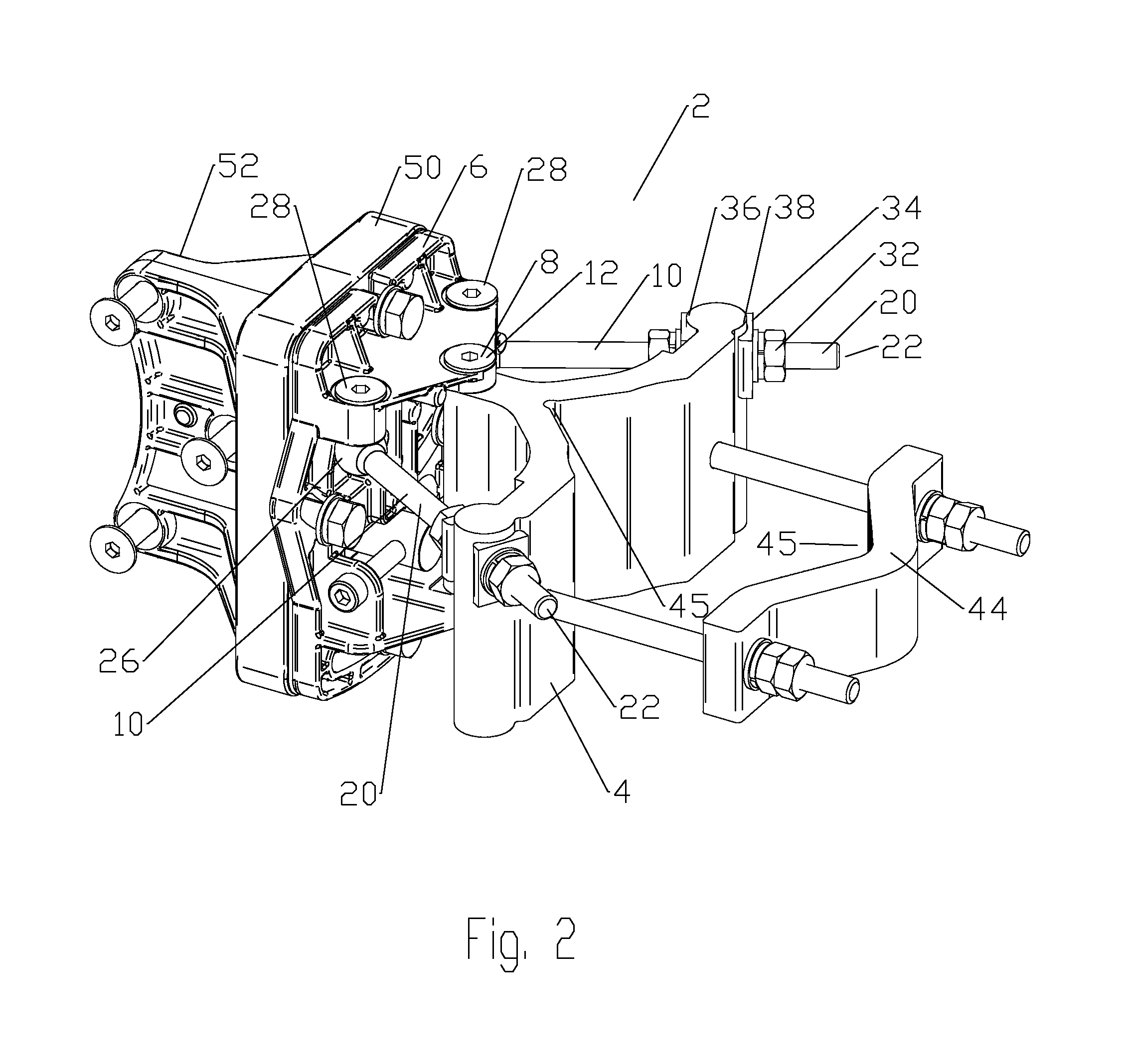
[0015]The inventors have discovered that a significant factor for alignment stability of an antenna mount is the lateral fit tolerances in the antenna mount between fasteners such as threaded bolts and their associated bolt holes. The inventors' testing has demonstrated that these fit tolerances can be a factor in permanent misalignment after simulated transient wind and / or ice loads are applied.

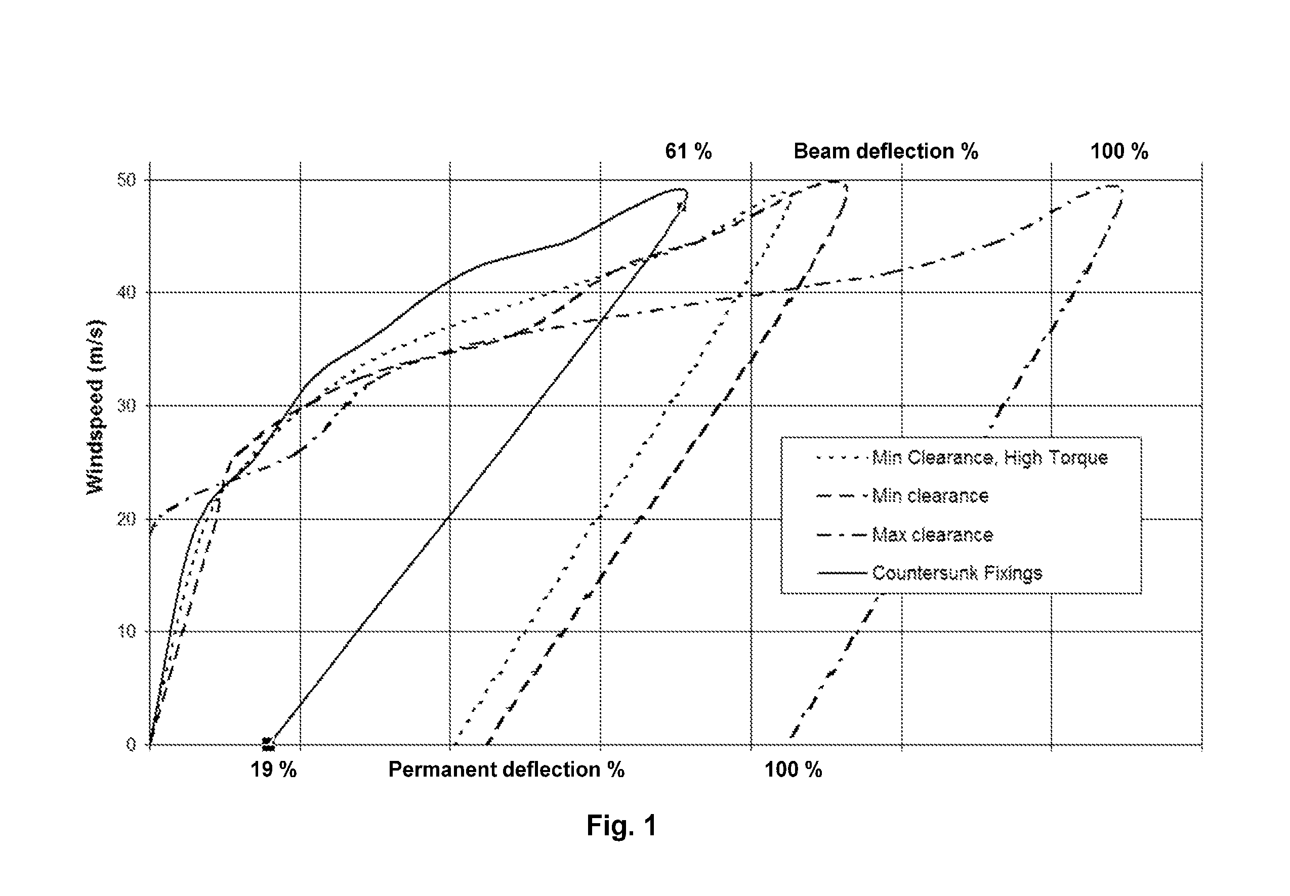
[0016]FIG. 1 shows the inventor's test data of changes in antenna mount angular alignment from an initial position as progressive levels of simulated windloading are applied and subsequently removed. Testing was performed upon embodiments of the same antenna mount configuration modeling pivot connection bolts and holes with maximum clearance, minimum clearance, minimum clearance with high torque and countersunk fixings (conical countersunk bolt heads and matching countersink bolt holes) with otherwise maximum clearance. Clearance is the amount of room between the unthreaded portion of the bo...


PUM

PropertyMeasurementUnit
Angleaaaaaaaaaa

Abstract

An antenna mount is provided with a pivot base and a pivot saddle rotatably coupled to the pivot base by a pivot connection and at least one pivot arm connection. The pivot connection is provided with dual opposing conical countersunk head pivot connection bolts seated within conical countersunk pivot connection bolt holes of the pivot saddle, the conical countersunk head pivot connection bolts extending through the conical countersunk pivot connection bolt holes of the pivot saddle to couple with the pivot base about a pivot axis.

Description

BACKGROUND[0001]1. Field of the Invention[0002]This invention relates to reflector antennas. More particularly, the invention relates to a cost efficient adjustable antenna mount with improved alignment stability.[0003]2. Description of Related Art[0004]Reflector antennas, for example terrestrial microwave reflector antennas, may be highly directional. To maximize electrical performance, the antenna mount of a reflector antenna may be finely adjustable for ease of obtaining a boresight alignment between antenna pairs forming an RF communications link. The antenna mount should maintain the selected alignment despite exposure over time to wind and / or ice loads acting upon the reflector antenna that, depending upon the installation location, may rise to extreme levels during short periods such as storms. As a distance to the target antenna increases, even very small alignment shifts become significant. Should the antenna mount lose the desired boresight alignment, for example due to tr...

Claims


Application Information

Patent Timeline
IPC IPC(8): H01Q1/12B23P17/00B23P15/00
CPCH01Q1/1228H01Q1/125Y10T29/49988H01Q3/02Y10T29/49H01Q3/08
Inventor RENILSON, IAN THOMASLEWRY, MATTHEW R.JEFFERSON, JAMES MICHAEL
Owner COMMSCOPE TECH LLC
Why Eureka
Try Eureka