
System and Method of Manufacturing a Composite Structure in a Closed Cavity Mold

a closed cavity mold and composite structure technology, applied in the field of composite systems, can solve the problems of composite structure failure, affecting the performance of composite structures, and recurring defects of composite structures

Active Publication Date: 2013-08-29
TEXTRON INNOVATIONS
View PDF5 Cites 12 Cited by
  • Summary
  • Abstract
  • Description
  • Claims
  • Application Information

AI Technical Summary

Benefits of technology

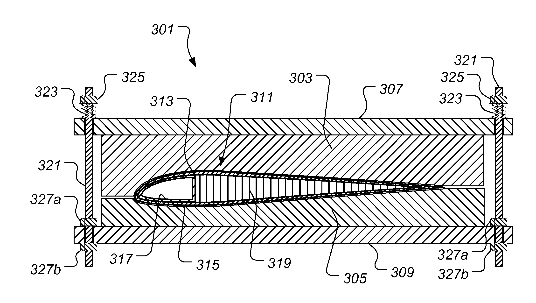
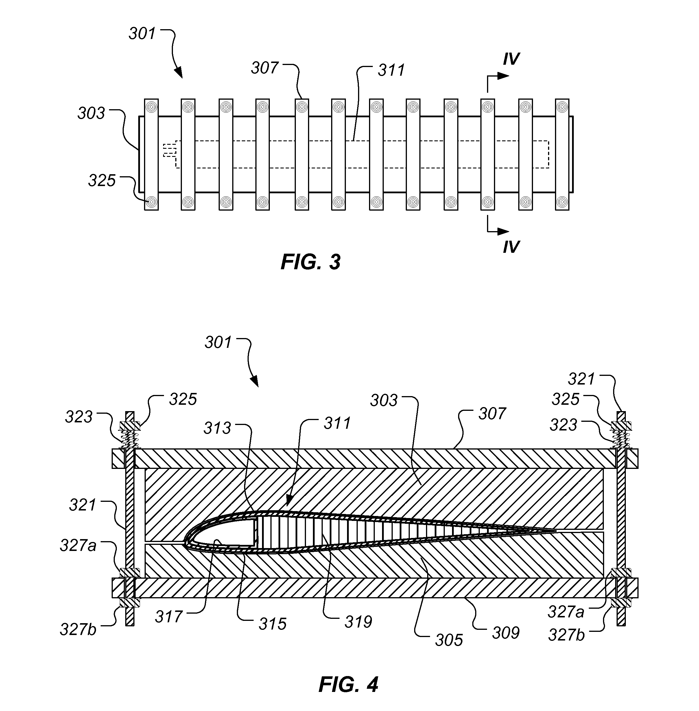
The present invention provides a system and method for manufacturing composite structures that has several advantages over conventional methods. Firstly, the system and method use springs to apply constant pressure during the curing cycle, without the need for expensive tools like hydraulic presses or autoclaves. This reduces the cost of manufacturing and compensates for any settling or shrinkage of the mold during the process, resulting in voids and porosity-free structures. Secondly, the system and method can be used in an ambient pressure environment, which avoids the restrictions and expense of using an autoclave. Lastly, the system and method allow for pressure to be supplied by springs, which ensures consistent pressure regardless of changes in ambient pressure.

Problems solved by technology

For example, a void, contour variation, or other defect in the cured composite structure is highly undesirable as the defect can cause the composite structure to fail and / or suffer a reduction in performance.
Further, the likelihood of defects can cause extensive examination of each cured composite structure to verify that a defect does not exist.
Although, there have been significant developments in composite systems and manufacturing techniques, defects in composite structures routinely occur.

Method used


Image

  • System and Method of Manufacturing a Composite Structure in a Closed Cavity Mold
  • System and Method of Manufacturing a Composite Structure in a Closed Cavity Mold
  • System and Method of Manufacturing a Composite Structure in a Closed Cavity Mold

Examples


Embodiment Construction

[0012]Illustrative embodiments of the system and method of the present application are described below. In the interest of clarity, not all features of an actual implementation are described in this specification. It will of course be appreciated that in the development of any such actual embodiment, numerous implementation-specific decisions must be made to achieve the developer's specific goals, such as compliance with system-related and business-related constraints, which will vary from one implementation to another. Moreover, it will be appreciated that such a development effort might be complex and time-consuming but would nevertheless be a routine undertaking for those of ordinary skill in the art having the benefit of this disclosure.

[0013]In the specification, reference may be made to the spatial relationships between various components and to the spatial orientation of various aspects of components as the devices are depicted in the attached drawings. However, as will be re...


PUM

PropertyMeasurementUnit
pressureaaaaaaaaaa
heataaaaaaaaaa
timeaaaaaaaaaa

Abstract

The present application relates to a method and system that can be utilized to manufacturing composite structures in a closed cavity mold. The tool system includes a closed cavity tool with spring members that when in compression apply pressure to a preform located within the closed cavity mold. During a curing cycle, the spring members provide substantially constant pressure to the preform, thereby preventing voids and porosity in the cured composite structure. Further, the substantially constant pressure, provided by the spring members, acts to more effectively conform the preform to the geometry defined by a void in the closed cavity mold during the curing cycle.

Description

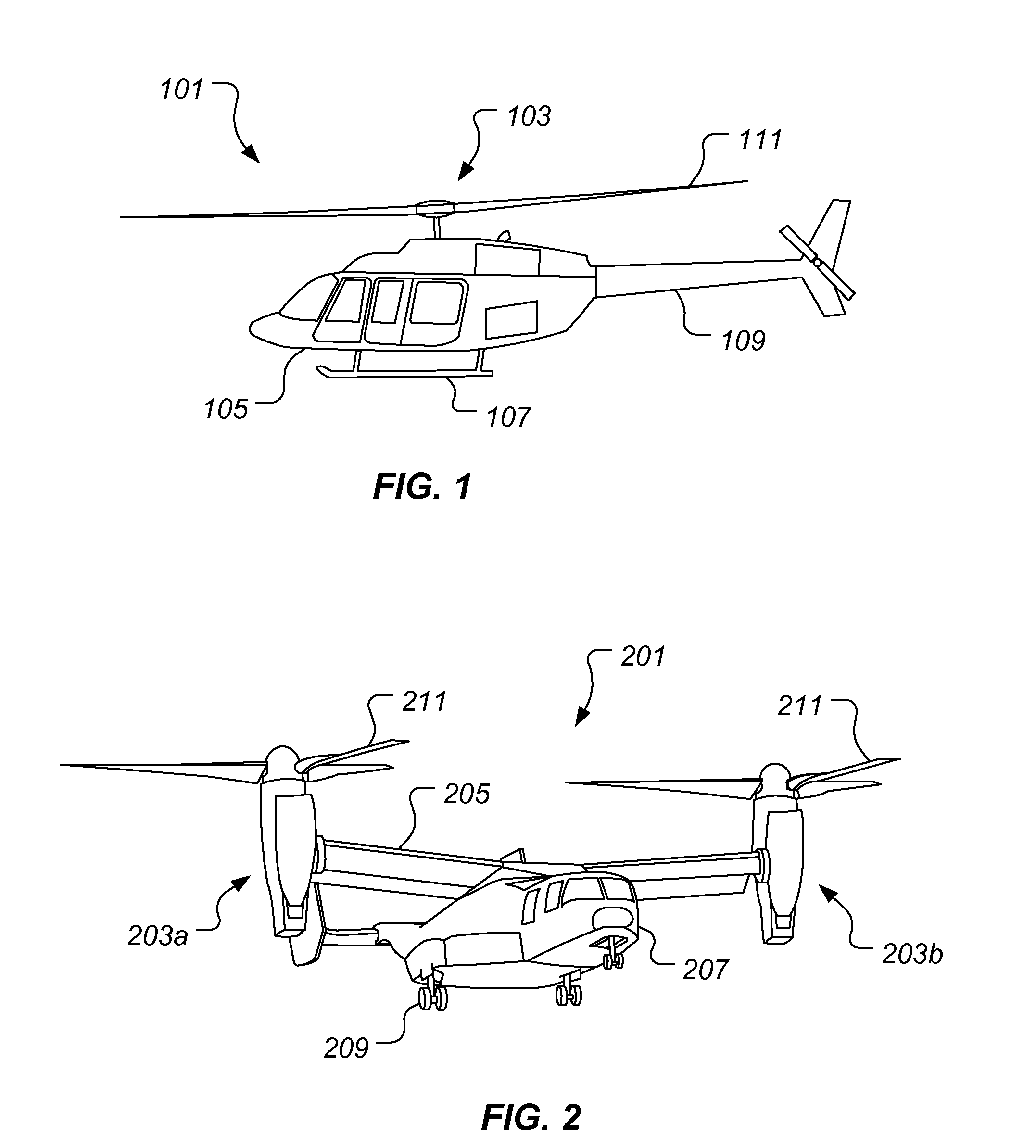
BACKGROUND[0001]1. Technical Field[0002]The present application relates in general to composite systems. More specifically, the present application relates to a method and system of manufacturing a composite structure in a closed cavity mold. The system and method of the present application are well suited for manufacturing composite parts for use in an aircraft; however, the system and method of the present application can be used to manufacture composite parts for use in a wide variety of industries.[0003]2. Description of Related Art[0004]The structural integrity of composite structures is partly dependent upon a consistency of the matrix of load bearing fibers in the risen binder. For example, a void, contour variation, or other defect in the cured composite structure is highly undesirable as the defect can cause the composite structure to fail and / or suffer a reduction in performance. Further, the likelihood of defects can cause extensive examination of each cured composite str...

Claims


Application Information

Patent Timeline
Patent Type & Authority Applications(United States)
IPC IPC(8): B29C35/08B29C33/02B29C35/02
CPCB29C70/46B29C33/20B29L2031/082B29C35/02B29C2035/0822B29C33/202B29K2105/0872
Inventor BISHOP, STEPHEN K.GREENBERG, ROBERT J.HENRY, FORREST W.
Owner TEXTRON INNOVATIONS
Learn More