Method of production of ignition coil and ignition coil produced by that method of production

a technology of ignition coil and production method, which is applied in the direction of magnets, inductances, magnetic bodies, etc., can solve the problems of reducing the insulation characteristics, breaking at the surface of the spool, and reducing so as to reduce the adhesion with the insulating material, eliminate the obstacle to automation of production, and thin the insulating film

Inactive Publication Date: 2013-08-29
DENSO CORP
View PDF0 Cites 0 Cited by
  • Summary
  • Abstract
  • Description
  • Claims
  • Application Information

AI Technical Summary

Benefits of technology

[0013]The thus produced ignition coil may be made one with an adhesion between the insulating film which is provided at the outer circumference of the center core and the insulating material which is filled at the inside of the ignition coil of not more than a predetermined value. Even if the insulating material shrinks, there is little breakage at the surfaces of the spools which are formed by plastic materials and the insulation characteristics can be maintained. Further, compared with the measure of covering the outer circumference of the core with a shrink-fit tube to reduce the adhesion with the insulating material, it is possible to make the insulating film thinner and eliminate the obstacle to automation of production of the ignition coil.

Problems solved by technology

In this regard, with the method of direct winding of the coils, there was the problem that when casting the metal material in a mold, shrinkage of the permeated epoxy resin due to curing caused breakage at the surfaces of the spools which were formed by plastic material and resulted in a decrease in the insulation characteristics.
A similar problem arises in a stick type ignition coil.
Shrinkage of the permeated epoxy resin due to curing caused breakage at the surfaces of the spools which were formed by plastic materials and lowered the insulation characteristics.
However, if covering the outer circumference of a core with a shrink-fit tube, there were the problems that since the tube had thickness, the outside diameter of the ignition coil increased, the shrink-fit tube could not exactly be fit to the outside shape of the core, and gaps ended up forming between the shrink-fit tube and core.
Further, when covering the outer circumference of the core by a shrink-fit tube, automation was difficult.

Method used


Image

  • Method of production of ignition coil and ignition coil produced by that method of production
  • Method of production of ignition coil and ignition coil produced by that method of production
  • Method of production of ignition coil and ignition coil produced by that method of production

Examples


Embodiment Construction

[0030]While the invention has been described by reference to specific embodiments chosen for purposes of illustration, it should be apparent that numerous modifications could be made thereto by those skilled in the art without departing from the basic concept and scope of the invention.

[0031]The present invention may be more fully understood from the description of preferred embodiments of the invention, as set forth below, together with the accompanying drawings.

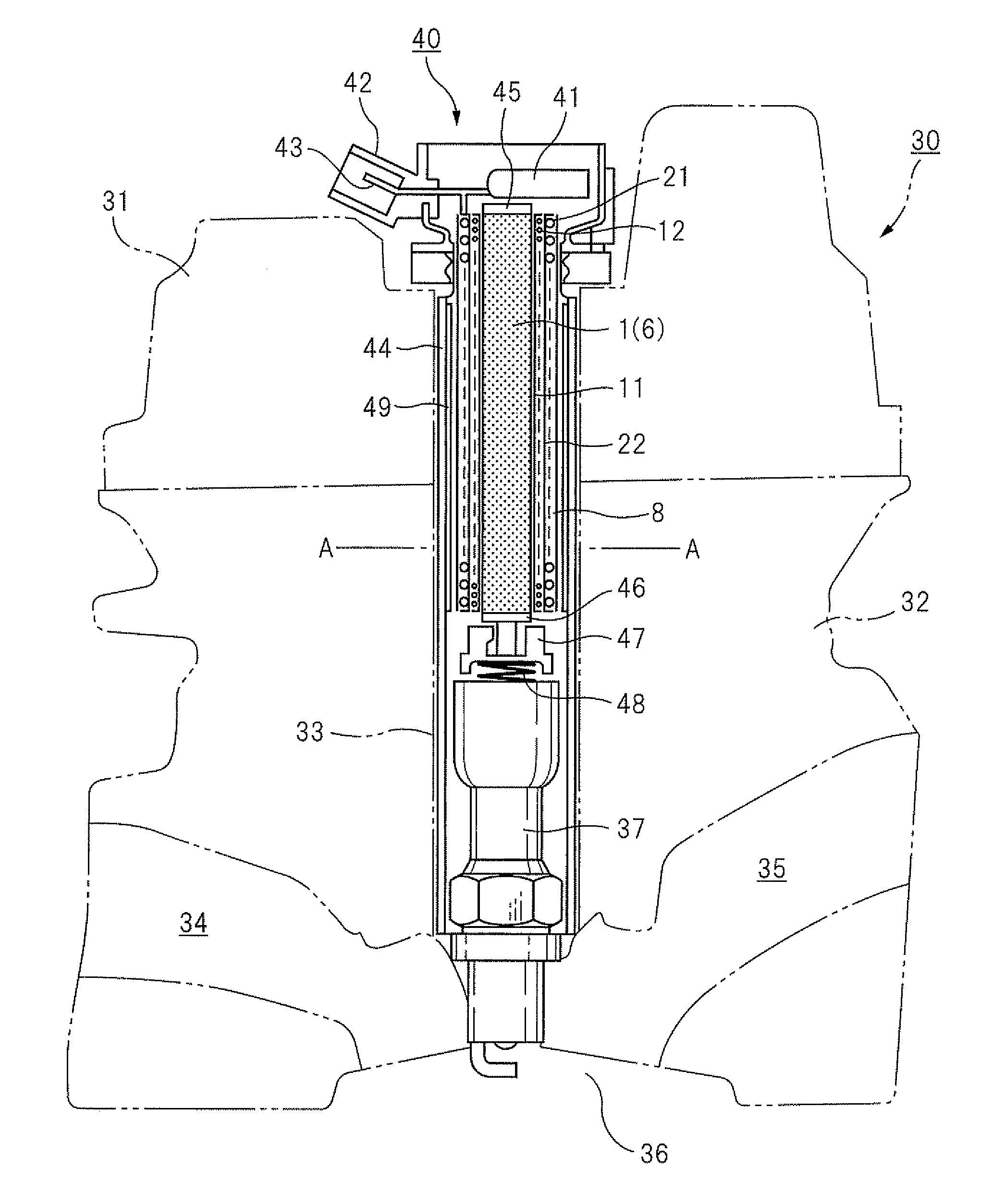
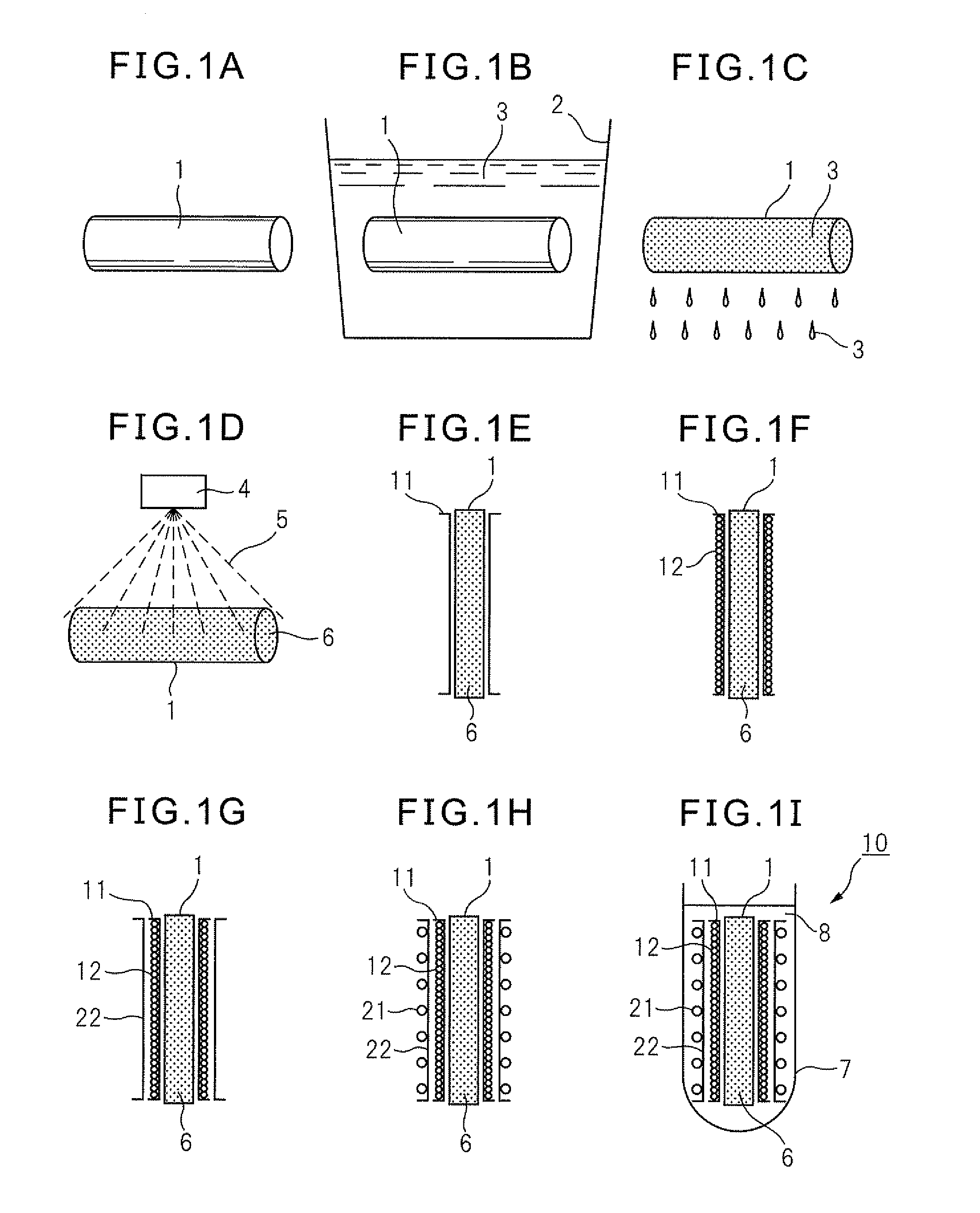
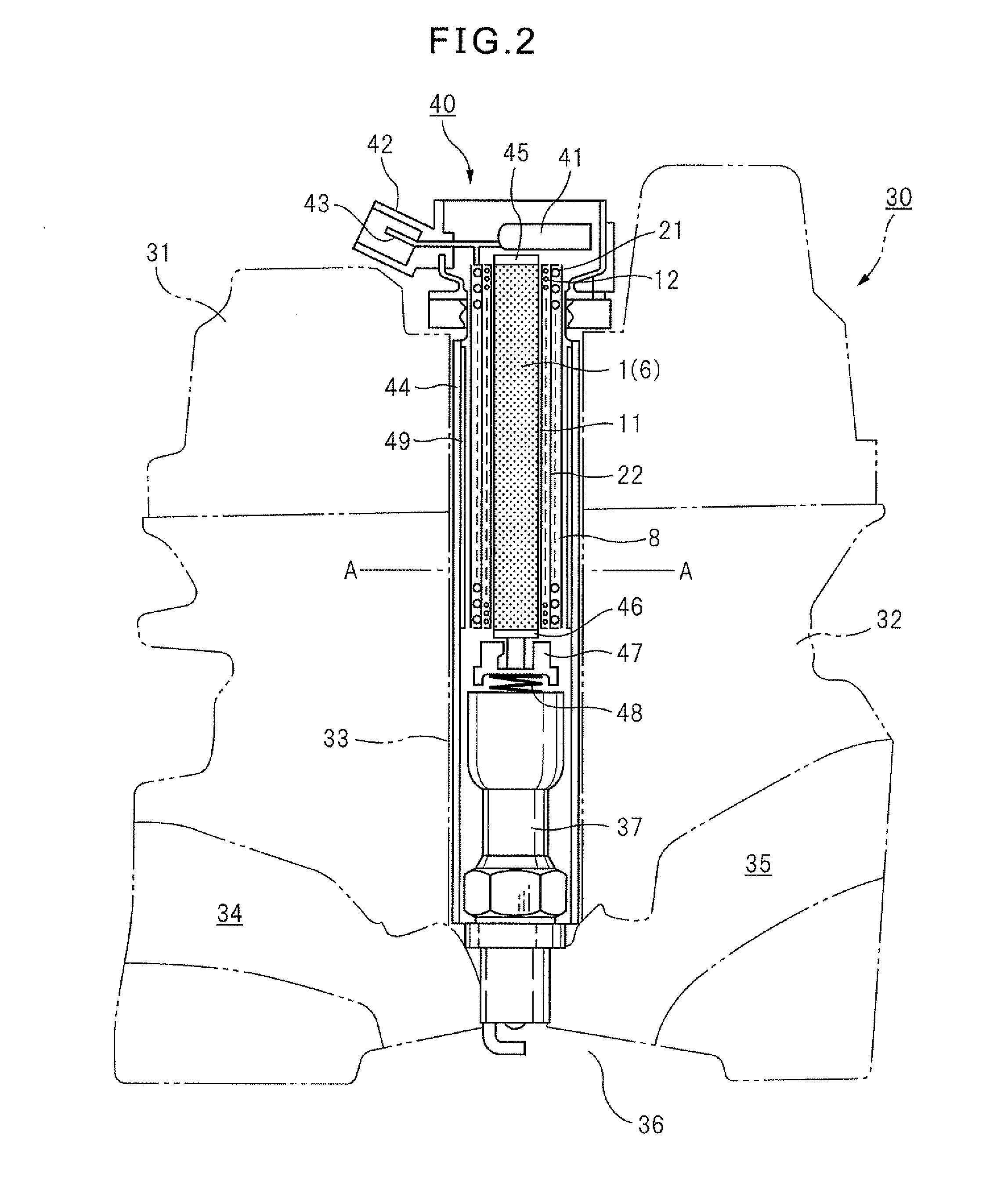
[0032]FIG. 1A to FIG. 1I are process diagrams for explaining a method of production of an ignition coil of the present invention. FIG. 1A is a view which shows a step of using a metal to form a rod-shaped center core 1. The center core 1 is generally produced by stacking thin silicon steel sheets in a direction perpendicular to the axial direction of the center core 1. The center core 1 of this embodiment is cylindrical in shape, but may also be prismatic in shape.

[0033]FIG. 1B is a view which shows a step of dipping the ce...


PUM

PropertyMeasurementUnit
timeaaaaaaaaaa
timeaaaaaaaaaa
voltageaaaaaaaaaa

Abstract

A method of production of an ignition coil which provided with a core so as to form a mold release film which enables reduction of the adhesion with an epoxy resin comprising using a metal to form a rod-shaped center core, dipping the formed center core in a liquid UV curing resin, raising the center core from the liquid and shaking off the excess UV curing resin, irradiating the center core with UV rays to cause the UV curing resin which is deposited on the center core to cure and form an insulating film, attaching a first spool to the outside of the insulating film and winding a secondary coil over it, attaching a second spool to the outside of the secondary coil and winding a primary coil over it, inserting these into a case, then injecting an insulating material into the case to thereby produce an ignition coil.

Description

BACKGROUND OF THE INVENTION[0001]1. Field of the Invention[0002]The present invention relates to a method of production of an ignition coil and an ignition coil which is produced by that method of production.[0003]2. Description of the Related Art[0004]In a vehicle which mounts a gasoline engine, gasoline which is injected into a cylinder is ignited by a spark plug. For this, an ignition system which uses an ignition coil is used. The ignition coil acts to convert low voltage of a battery to a high voltage so that a spark is generated at the spark plug. Such an ignition coil is configured by a core comprised of a stack of iron sheets with a large magnetic permeability at its center (hereinafter referred to simply as a “core”) around which a primary coil and a secondary coil are wound.[0005]As one technique for reduction of size and increase of output of the ignition coil, there is the art of direct winding around the center core. The advantages of this art are the ability to secure ...

Claims


Application Information

Patent Timeline
Patent Type & Authority Applications(United States)
IPC IPC(8): H01F41/04H01F27/32
CPCH01F27/022H01F38/12Y10T29/4902H01F41/04H01F27/327H01F41/005
Inventor MAKISHIMA, TATSUNORIAOKI, TAKASHI
Owner DENSO CORP
Why Eureka
Try Eureka