
Method and system for full path analysis

a path analysis and path analysis technology, applied in the field of information technology, can solve the problems of cumbersome configuration, difficult use, and high deployment cost of existing systems for tracking people in retail stores

Active Publication Date: 2013-08-29
RETAILNEXT
View PDF3 Cites 36 Cited by
  • Summary
  • Abstract
  • Description
  • Claims
  • Application Information

AI Technical Summary

Benefits of technology

The patent describes a system that allows non-technical users to create a model of a space using a camera and a floor plan. The system uses a flexible polynomial to account for variations in camera lenses and allows for easy placement of calibration points. The model can be used to map points in the camera image to locations on the floor plan. The technical effect is a simplified and user-friendly method for creating a detailed model of a space that can be easily shared and used by others.

Problems solved by technology

Existing systems for tracking people in a retail store are cumbersome to configure, difficult to use, and expensive to deploy.

Method used


Image

  • Method and system for full path analysis
  • Method and system for full path analysis
  • Method and system for full path analysis

Examples


Embodiment Construction

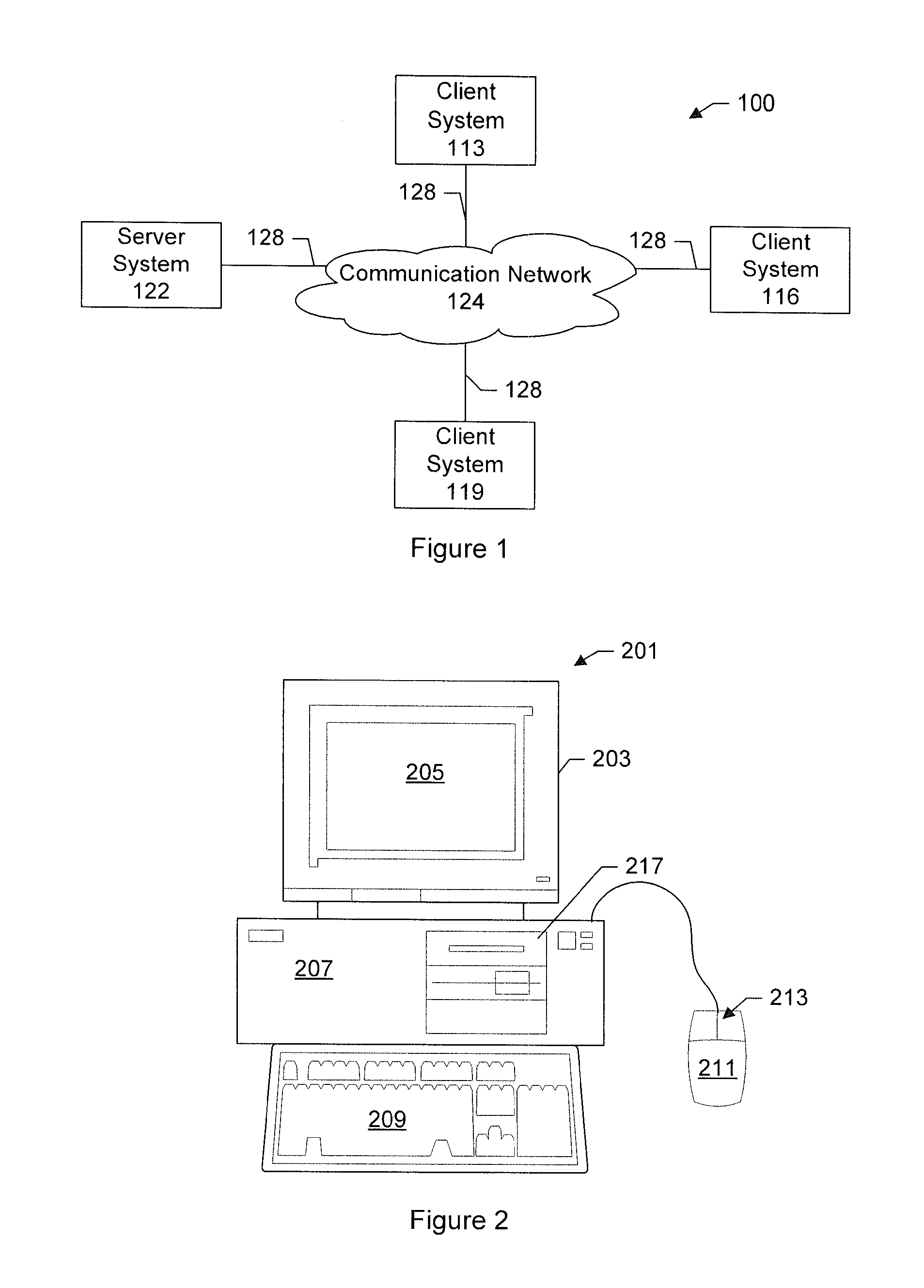
[0051]FIG. 1 is a simplified block diagram of a distributed computer network 100. Computer network 100 includes a number of client systems 113, 116, and 119, and a server system 122 coupled to a communication network 124 via a plurality of communication links 128. There may be any number of clients and servers in a system. Communication network 124 provides a mechanism for allowing the various components of distributed network 100 to communicate and exchange information with each other.

[0052]Communication network 124 may itself be comprised of many interconnected computer systems and communication links. Communication links 128 may be hardwire links, optical links, satellite or other wireless communications links, wave propagation links, or any other mechanisms for communication of information. Various communication protocols may be used to facilitate communication between the various systems shown in FIG. 1. These communication protocols may include TCP / IP, HTTP protocols, wireless...


PUM


Abstract

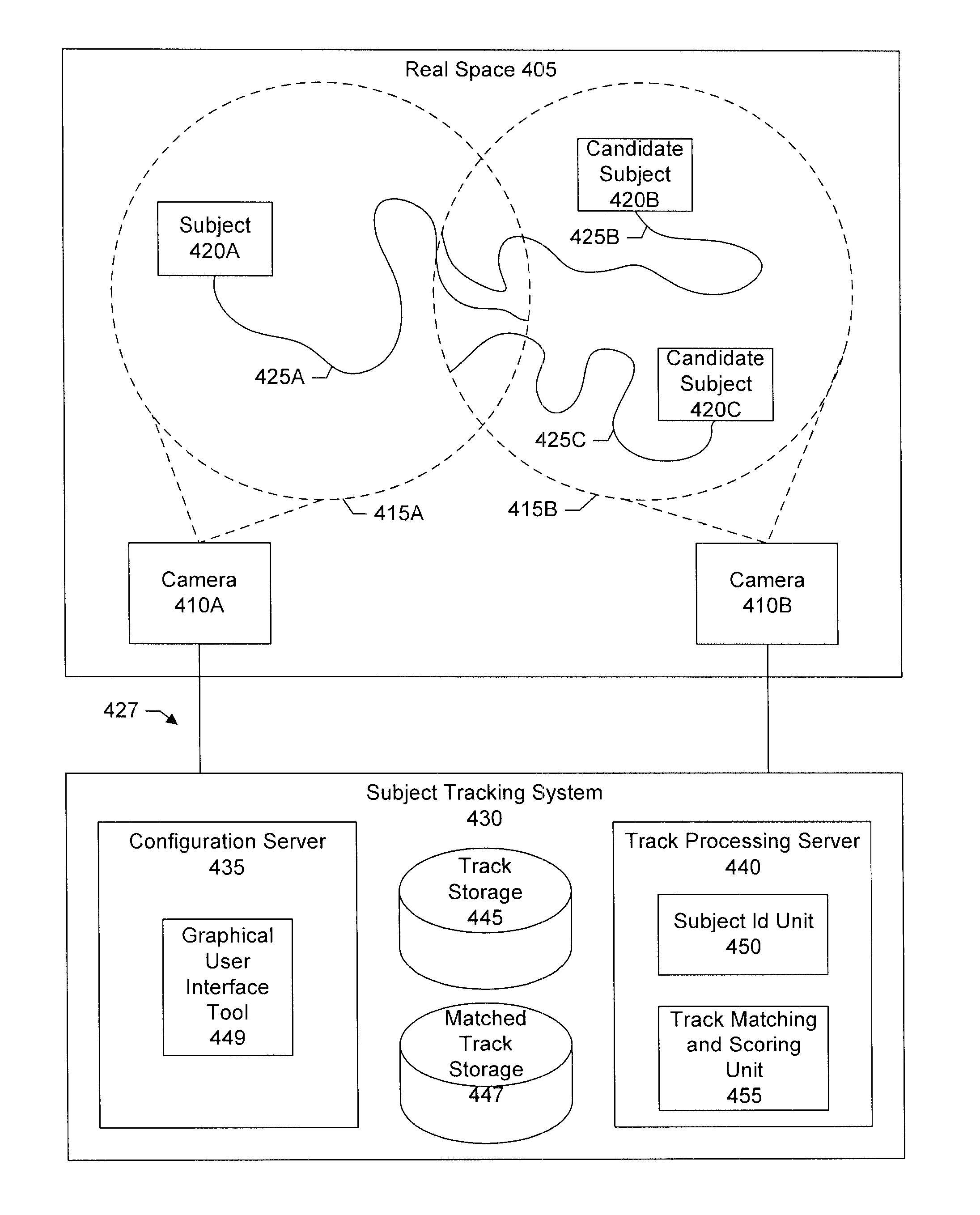
A space is modeled using images from a set of cameras in the space. An easy to use tool is provided that allows users to identify a reference location in an image and a corresponding reference location on a floor plan of the space. Based on these correspondences, a model is generated that can map a point in a camera's view to a point on the floor plan, or vice-versa. Subjects moving through the space are identified and tracked using the model and attributes associated with a subject. In a specific implementation, the attributes include velocity, color, size, and position. In a specific implementation, the space is a retail store and the subjects are customers browsing through the retail store.

Description

CROSS-REFERENCE TO RELATED APPLICATIONS[0001]This patent application claims priority to U.S. provisional patent application 61 / 605,054, filed Feb. 29, 2012, and is incorporated by reference along with all other references cited in this application.BACKGROUND[0002]The present invention relates to the field of information technology, including, more particularly, to systems and techniques for tracking subjects.[0003]Tracking subjects through a real world space offers benefits in a variety of areas including commercial, business, corporate, security, government, science, and others. For example, brick and mortar businesses have long desired to gather data that would allow them to better understand customer behavior. Such data can be used to make decisions about merchandising, advertising, pricing, staffing, design new in-store concepts, and, in particular, understand how customers interact with store displays, make correlations with sales data, calculate conversion rates, identify good...

Claims


Application Information

Patent Timeline
IPC IPC(8): G06K9/60
CPCG06K9/60G06K9/00771G06V20/52G06V10/20
Inventor SHAW, GEORGE
Owner RETAILNEXT
Learn More