Image Display Device

Active Publication Date: 2013-08-29
FUNAI ELECTRIC CO LTD
View PDF1 Cites 14 Cited by
  • Summary
  • Abstract
  • Description
  • Claims
  • Application Information

AI Technical Summary

Benefits of technology

[0015]According to the present invention, the laser source is relaxation oscillated using the first and second waveform patterns that include an on and an off period. At this time, the on period for the second pixel of which the period for displaying the pixel is set longer in order to compensate for the difference in the scanning speed is segmented more than that for the first pixel of which the period for displaying the pixel is set shorter so that a greater number of relaxation oscillations are generated. As a result, a reduction in the time ratio of the relaxation oscillations accompanying the elongation of the period for displaying the pixel can be suppressed. As a result, speckle noise can be effectively reduced not only in the region of a pixel of which the period for displaying

Problems solved by technology

In this laser projector, microscopic flickers, which are referred to as speckl

Method used


Image

  • Image Display Device
  • Image Display Device
  • Image Display Device

Examples


Embodiment Construction

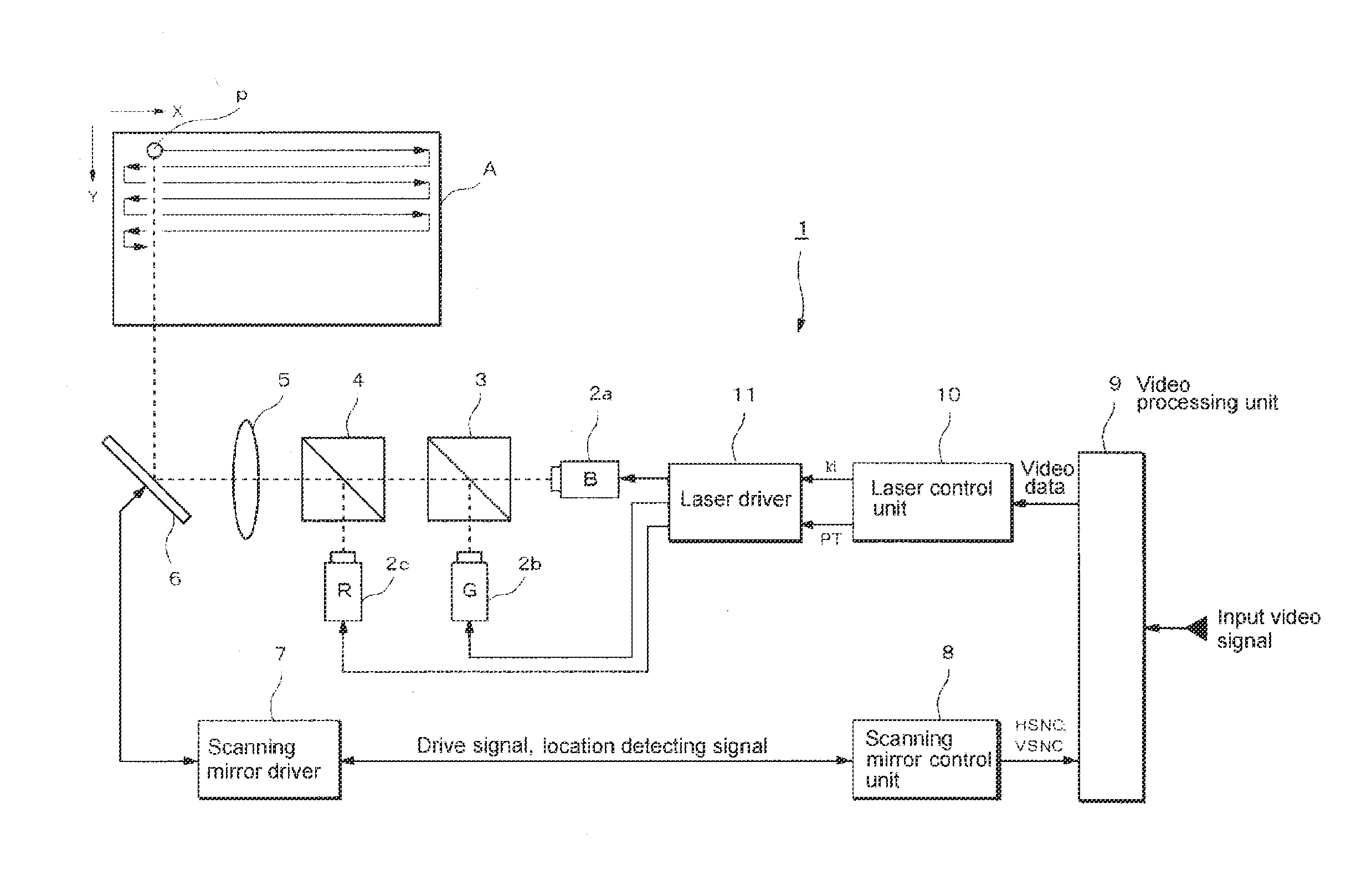
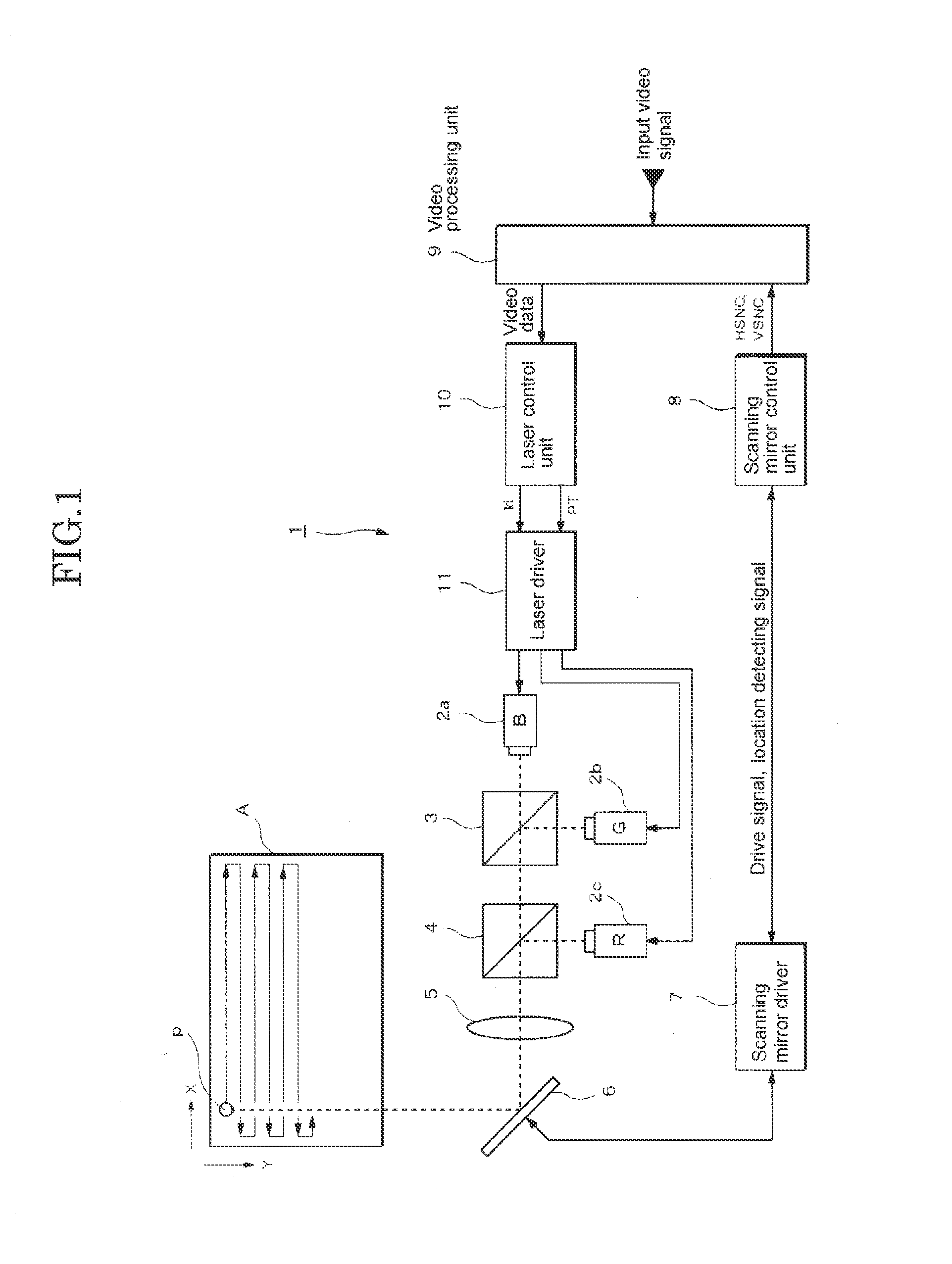
[0030]FIG. 1 is a block diagram showing the structure of the laser projector according to the present embodiment. This laser projector 1 is formed mainly of laser sources 2a to 2c, various types of optical elements 3 to 5, a scanning mirror 6 and various types of driving / control units 7 to 11. The laser projector 1 combines laser beams for the red, blue and green components, and then projects them on a projection surface A, such as a screen or a wall, so that a color image corresponding to a video signal is displayed on the projection surface A. The laser projector 1 uses laser beams having extremely high directivity, and therefore has an excellent advantage where it is unnecessary to adjust the focal point in accordance with the distance to the projection surface A.

[0031]The laser sources 2a to 2c are driven independent of each other by a drive current that is individually supplied from the laser driver 11. As a result, laser beams having a certain wavelength, such as the blue comp...


PUM


Abstract

The image display device resolves inconsistency in the brightness of the image while effectively reducing local speckle noise that remains due to the laser scanning of which the scanning speed fluctuates. A waveform pattern (PT2) that includes an on period and an off period within the pixel displaying period (T2) is selected for the center pixel (P512). A waveform pattern (PT1) that includes an on period and an off period within the pixel displaying period (T1) that is longer than the pixel displaying period (T2) is selected for the side pixel (P1) or (P1023) that is scanned at a scanning speed slower than that for the center pixel (P512). Here, the on period in the waveform pattern (PT1) is segmented more than the on period in the waveform pattern (PT1), and the time ratio of the on period accounting for the waveform pattern (PT1) is smaller than the time ratio of the on period accounting for the waveform pattern (PT2).

Description

TECHNICAL FIELD[0001]The present invention relates to an image display device for displaying an image on a projection surface through scanning of a laser beam.BACKGROUND ART[0002]Patent Document 1 discloses a laser projector for displaying an image on a projection surface by reflecting a laser beam emitted from a laser source from a scanning mirror so as to be projected onto this projection surface. The scanning mirror is freely displaced in the directions along two axes, and the mirror is oscillated with a resonance frequency particular to the mirror. In this laser projector, microscopic flickers, which are referred to as speckle noise, become a problem caused by the coherence particular to the laser beam. In order to reduce speckle noise, various techniques have been proposed, and as one of them, Patent Document 2 discloses a technique for using relaxation oscillations of the laser source. In this technique, a rectangular waveform pattern where on and off alternate is used to driv...

Claims


Application Information

Patent Timeline
IPC IPC(8): G02B27/48
CPCG02B27/48H04N9/3135H04N9/3129G09G3/02G02B26/10G03B21/14
Inventor CHIKAOKA, ATSUHIKO
Owner FUNAI ELECTRIC CO LTD
Why Eureka
Try Eureka