Network system and frame communication method

a network system and communication method technology, applied in the field of network systems, can solve problems such as deterioration of achieve the effect of improving network flexibility and extensibility

Inactive Publication Date: 2013-08-29
NEC CORP
View PDF5 Cites 7 Cited by
  • Summary
  • Abstract
  • Description
  • Claims
  • Application Information

AI Technical Summary

Benefits of technology

[0015]According to the present invention, frames transmitted from the node are divided into the control frames and the data frames. The data frames whose amount of information is enormous as compared with the control frames are transferred without through a specific route. That is, the communication system according to the present invention is freed from the constraint that there exists a device through which the data frames, which greatly contributes to network performance, invariably go. It is therefore possible to improve network flexibility and extensibility.

Problems solved by technology

This causes deterioration of network flexibility and extensibility.

Method used


Image

  • Network system and frame communication method
  • Network system and frame communication method
  • Network system and frame communication method

Examples


modification example

1-3. Modification Example

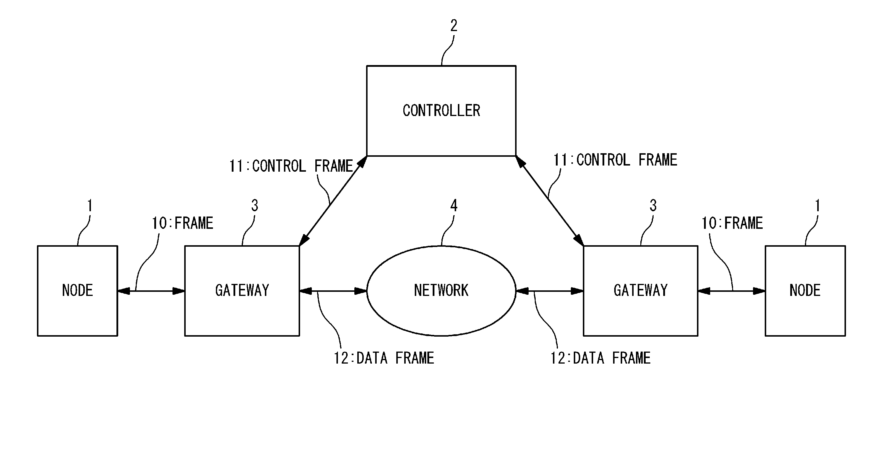
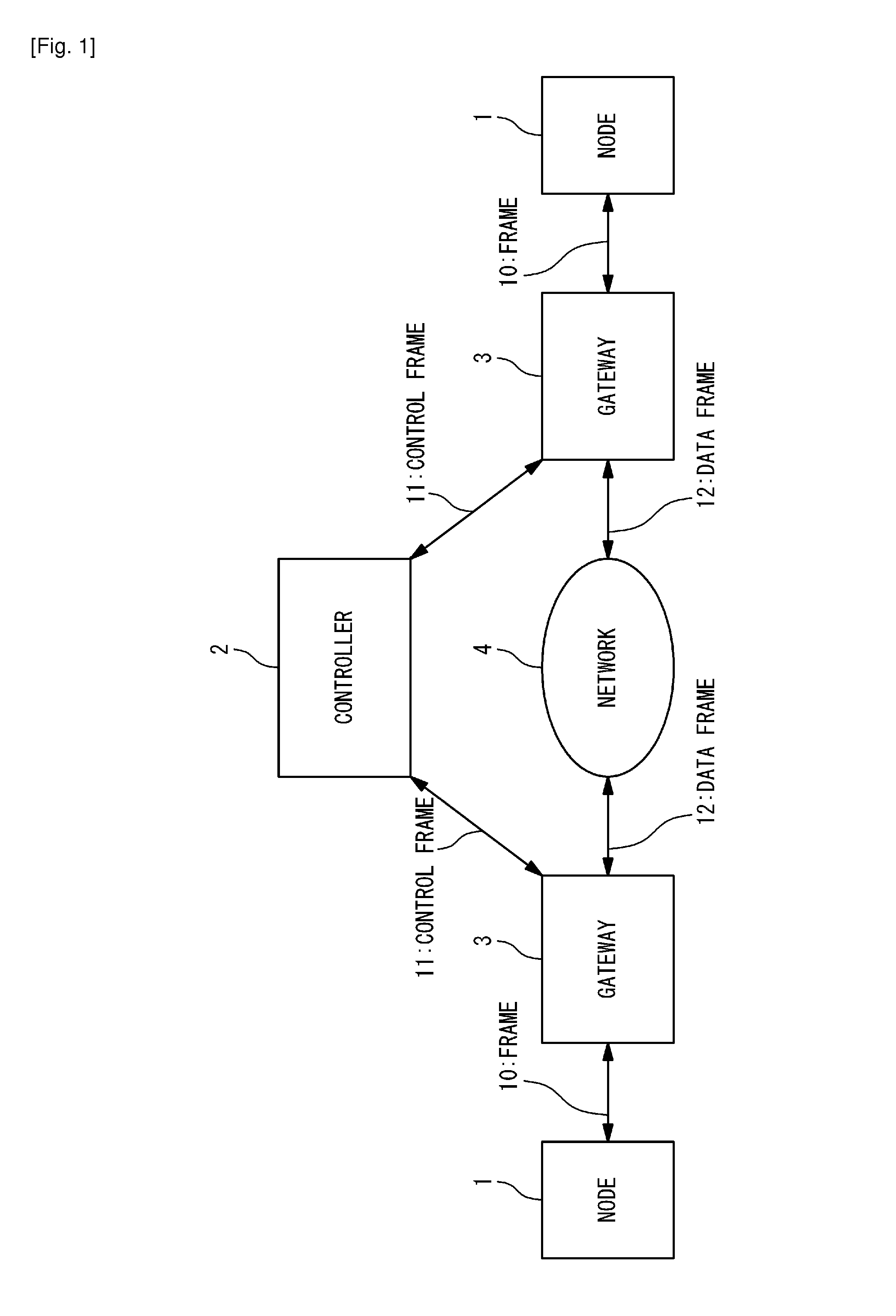
[0070]FIG. 5 is a block diagram showing a modification example of the network system according to the present exemplary embodiment. According to the present modification example, the gateway 3 is built in a network device within the node 1. More specifically, the node 1 has a network card 40, and the gateway 3 is built in the network card 40. The gateway 3 in FIG. 5 is the same as the gateway 3 in FIG. 1 except for the installation location. According to the present modification example, functions are concentrated in the node 1 and thus the network flexibility is expected to be further improved.

[0071]FIG. 6 is a block diagram showing a hardware configuration example of the controller 2 according to the present exemplary embodiment. The functions of the controller 2 are implemented in a single server 90. The server 90 has a network interface card (NIC) 100, a processor (CPU) 101 and a memory 102. The functions of the controller 2 are achieved by cooperation o...

first example

2-1. First Example

[0119]FIG. 12 is a conceptual diagram showing protocol stack according to the present exemplary embodiment. A usual FCoE protocol stack consists of FC4 to FC2 layers associated with the FC, an FCoE mapping layer, and a MAC layer and a physical layer associated with the Ethernet. According to the present exemplary embodiment, as shown in FIG. 12, the retransmission control and reordering function is installed in a layer (so-called L2.5 layer) between the FCoE mapping layer and the MAC layer.

[0120]The retransmission control function can be achieved by, for example, R2D2 described in B. Atikoglu et al., “R2D2: RAPID AND RELIABLE DATA DELIVERY IN DATA CENTERS”, Stanford University (http: / / forum.stanford.edu / events / posterslides / R2D2Rap idandReliableDataDeliveryinDataCenters.pdf).

[0121]It should be noted that in the case where the U / C separation function (gateway 3) is built in the network card 40 of the node 1 as shown in FIG. 5, the U / C separation function also is inst...

second example

2-2. Second Example

[0128]There may be a situation where a part of nodes in the network system does not support the retransmission control and reordering function. FIG. 15 shows an example of such the situation. A node 1B (node number: #1, #2, #4) is provided with the retransmission control and reordering function (retransmission control and reordering unit 210). Whereas, the node 1 (node number: #3) is not provided with the retransmission control and reordering function (retransmission control and reordering unit 210).

[0129]The retransmission control and reordering processing only makes sense if a source node and a destination node both have the function. If at least one of the source node and the destination node does not have the retransmission control and reordering function, the retransmission control and reordering processing needs to be deactivated. However, in general, whether or not both of them have the retransmission control and reordering function is not known until the E...


PUM


Abstract

A network system has: a node performing transmission/reception of a frame based on FCoE; a network; a controller performing management of the node and the network; and a gateway provided with respect to the node. The frame is classified into a control frame and a data frame. The gateway determines whether a frame received from the node is the control frame or the data frame, forwards the control frame to the controller, and forwards the data frame to the network. The controller performs the management based on the control frame received from the gateway. The network transfers the data frame received from the gateway to a destination node without through the controller. The node has a retransmission control and reordering unit configured to perform retransmission control and reordering processing with respect to the data frame.

Description

TECHNICAL FIELD [0001]The present invention relates to a network system that performs frame communication.BACKGROUND ART [0002]One of technologies for performing communication on a network is “data encapsulation”. The details are as follows.[0003]A data transferred between networks constitutes its form in accordance with a communication system used at the time of the transfer. The communication on the network is performed through a plurality of layers, as represented by OSI Reference Model and TCP / IP stack. Therefore, the form of the data needs to be capable of supporting specification of each layer. In general, a data consists of a header and a payload. The header includes a content that serves as a control data at a specific layer, and a communication standard at that layer interprets the content of the header to forward the payload to another layer. At each layer, the header is added ahead of the payload at a time of transmission and the header is removed at a time of reception. ...

Claims


Application Information

Patent Timeline
Patent Type & Authority Applications(United States)
IPC IPC(8): H04L12/56
CPCH04L1/18H04L49/25H04L49/357H04L45/72
Inventor KAMIYA, SATOSHIICHINO, KIYOHISAKOBAYASHI, NORIAKI
Owner NEC CORP
Why Eureka
Try Eureka