
Method and evaluation device for determining the position of a structure located in an object to be examined by means of x-ray computer tomography

a technology of x-ray computer tomography and structure, which is applied in the direction of image enhancement, image analysis, instruments, etc., can solve the problems of difficult measurement of components to check whether the required manufacturing tolerances are adhered to, difficult distance determination, and grey value smears, etc., to achieve the effect of simple, precise and precis

Inactive Publication Date: 2013-08-29
MAHLE INT GMBH
View PDF3 Cites 1 Cited by
  • Summary
  • Abstract
  • Description
  • Claims
  • Application Information

AI Technical Summary

Benefits of technology

The patent is about a way to accurately determine the position of a structure inside an object or component using X-ray computer tomography. The goal is to make the process easier, more precise, and automatic.

Problems solved by technology

This measuring of components to check whether the required manufacturing tolerances are adhered to is, however, difficult.
Although, in principle, the distance between two selected points, for example to determine the position of an interior structure in the component, can be determined from the volume data record of the component to be investigated, which is determined by means of X-ray computer tomography, this distance determination is made more difficult by interfering effects, such as, for example, noise, scattered radiation or beam hardening, as these interfering effects change or falsify the grey values of the voxels in the volume data record.
Moreover, grey value smears, which make a dimensional measurement of the component more difficult, occur in the transition between two different media, such as, for example, the object material and the air located in an interior cavity.

Method used


Image

  • Method and evaluation device for determining the position of a structure located in an object to be examined by means of x-ray computer tomography
  • Method and evaluation device for determining the position of a structure located in an object to be examined by means of x-ray computer tomography
  • Method and evaluation device for determining the position of a structure located in an object to be examined by means of x-ray computer tomography

Examples


Embodiment Construction

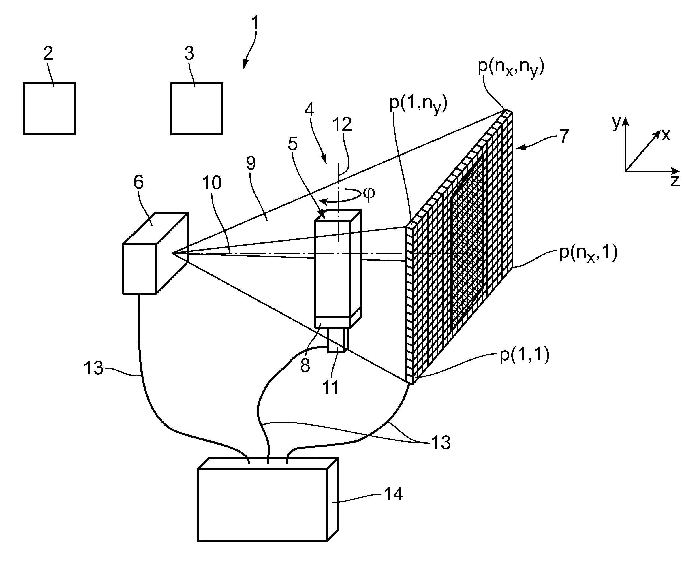
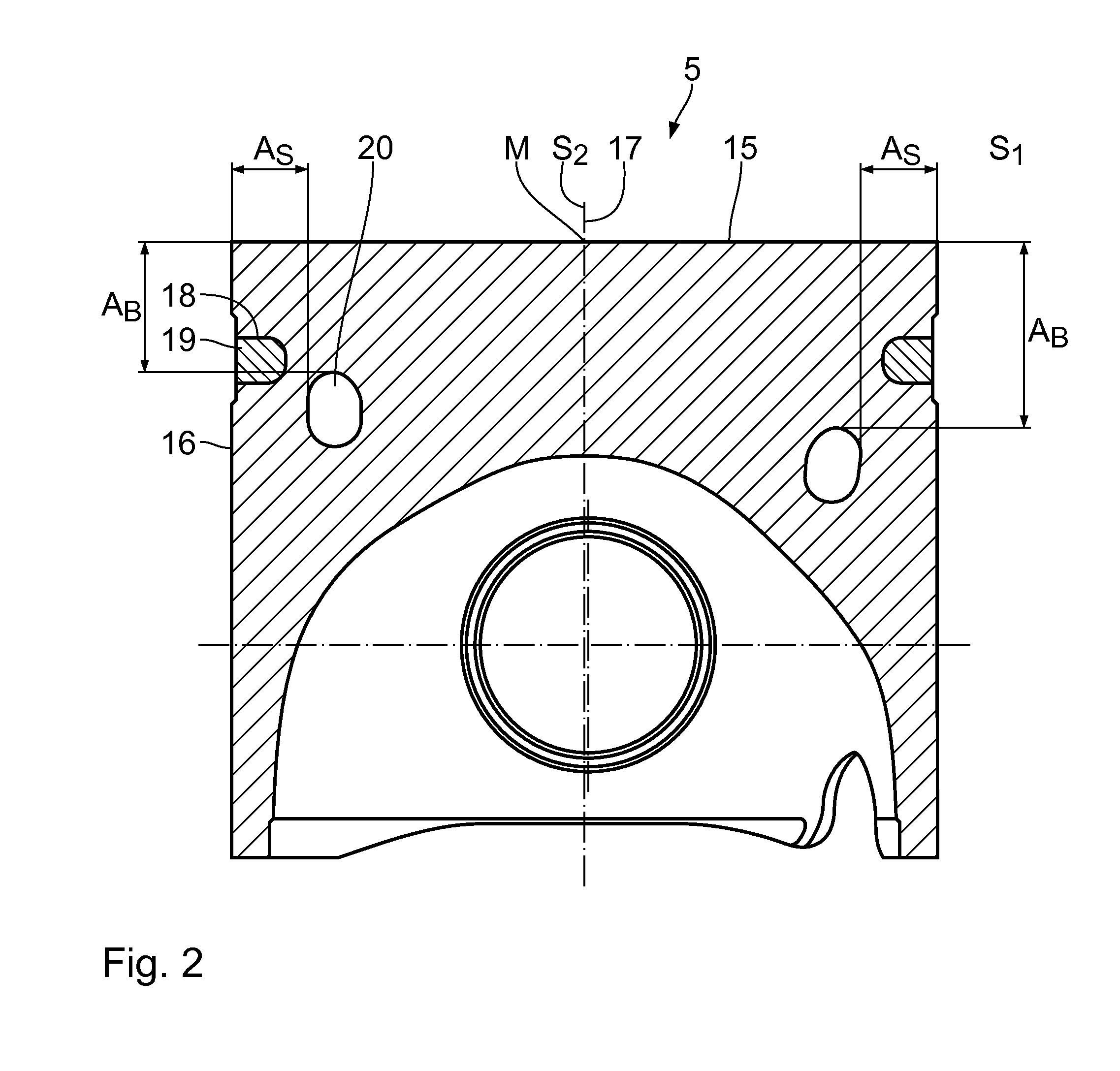
[0076]An inline test system 1 has a production device 2, a handling apparatus 3 and an X-ray computer tomograph 4. The inline test system 1 is used to test objects 5 or components in the form of pistons directly after they have been produced. The pistons 5 are, for example, cylinder pistons. The pistons 5 produced in the production device 2 can be fed by means of the handling apparatus 3 to the X-ray computer tomograph 4, which carries out a test on the pistons 5 produced.

[0077]The X-ray computer tomograph 4 has an X-ray source 6 and an associated X-ray detector 7. Arranged between the X-ray source 6 and the X-ray detector 7 is an object carrier 8, by means of which the pistons 5 to be investigated can be positioned.

[0078]The X-ray source 6 is used to produce an X-radiation 9 emitted conically in the direction of the pistons 5. The X-radiation 9 runs substantially symmetrically with respect to a center longitudinal axis 10 of the X-ray computer tomograph 4. The X-ray source 6 is, fo...


PUM


Abstract

In a method and an evaluation device for determining the position of a structure located in an object to be investigated by means of X-ray computer tomography, a cutting data record, which images the object in a cutting plane, is determined from a volume data record of the object. The cutting data record is binarized to form a binary data record, in which the structure voxels imaging the structure and the surface voxels imaging an object surface are determined. To determine the position, a distance data record is produced in such a way that a distance value, which characterizes the smallest distance of the respective distance voxel from the surface voxels, is assigned to each distance voxel of the distance data record. The distance voxels corresponding to the structure voxels are then determined and the associated distance values evaluated.

Description

CROSS REFERENCE TO RELATED APPLICATIONS[0001]This application is a United States National Phase Application of International Application PCT / EP2011 / 069083 and claims the benefit of priority under 35 U.S.C. §119 of German Patent Application Serial No. 10 2010 043 226.1 filed Nov. 2, 2010, the entire contents of which are incorporated herein by reference.FIELD OF THE INVENTION[0002]The invention relates to a method and an evaluation device for determining the position of a structure located in an object to be investigated by means of X-ray computer tomography.BACKGROUND OF THE INVENTION[0003]The automatic and destruction-free testing of objects or components by means of X-ray computer tomography is increasingly growing in importance in quality assurance. The challenge is, on the one hand, to reliably recognize material faults, such as, for example, pores or cracks. On the other hand, the dimensional measuring of components is of great importance. This measuring of components to check ...

Claims


Application Information

Patent Timeline
IPC IPC(8): G06T7/00
CPCG06T7/004G06T2207/10081G06T7/0004G06T2207/30164G06T2207/20041G06T7/70G06T7/00
Inventor OECKL, STEVENSCHON, WERNERSCHNELL, HOLGERMULLER, GUSTAVPAPADOPOULUS, IOANNIS
Owner MAHLE INT GMBH
Learn More