
Turbocharger, notably for a combustion engine

a technology of turbocharger and combustion engine, which is applied in the direction of machines/engines, rigid support of bearing units, liquid fuel engines, etc., can solve the problems of increasing mounting costs and indentations on the raceways of rolling bearings, and achieves the effect of simple manufacturing and economics

Inactive Publication Date: 2013-08-29
AB SKF
View PDF5 Cites 6 Cited by
  • Summary
  • Abstract
  • Description
  • Claims
  • Application Information

AI Technical Summary

Benefits of technology

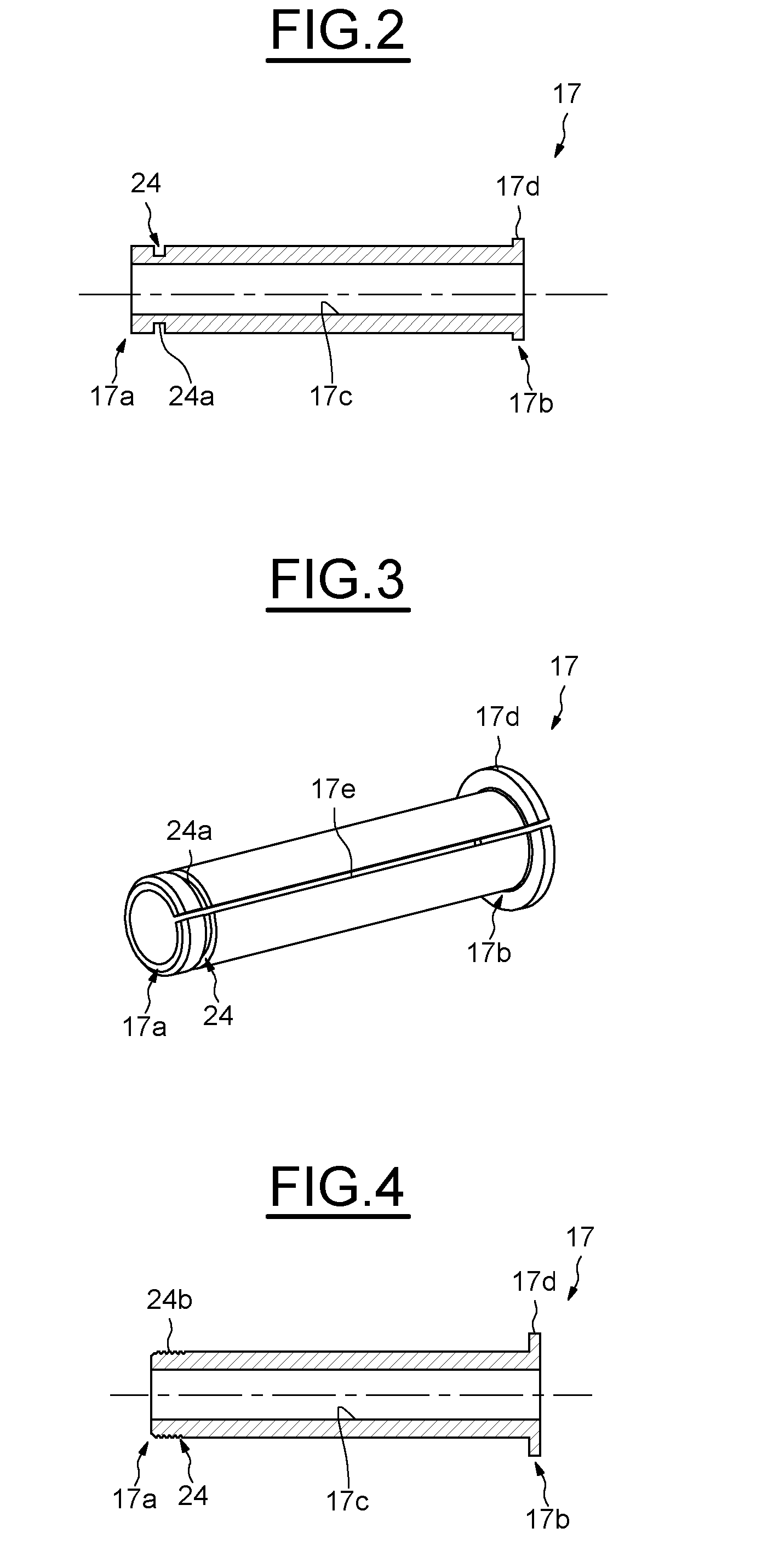
The present invention is about a turbocharger that is easy to manufacture, economic and can disassemble the rollings bearings without damaging them or the shaft. The invention includes an intermediate sleeve between the rolling bearing and the shaft, which allows for the shaft to be disassembled without damaging the rolling bearing. The sleeve has a "first end" that can be reached with an external mounting tool. The technical effect of this invention is that it simplifies the process of disassembling the rollings bearings and shaft without causing any damage.

Problems solved by technology

However, in order to disassemble the rolling bearings from the shaft, an axial load is generally applied to the shaft, which may lead to indentations on the raceways of the rolling bearings.
Replacing the rolling bearings after all disassembly procedures leads to an increase of the mounting cost.

Method used


Image

  • Turbocharger, notably for a combustion engine
  • Turbocharger, notably for a combustion engine
  • Turbocharger, notably for a combustion engine

Examples


Embodiment Construction

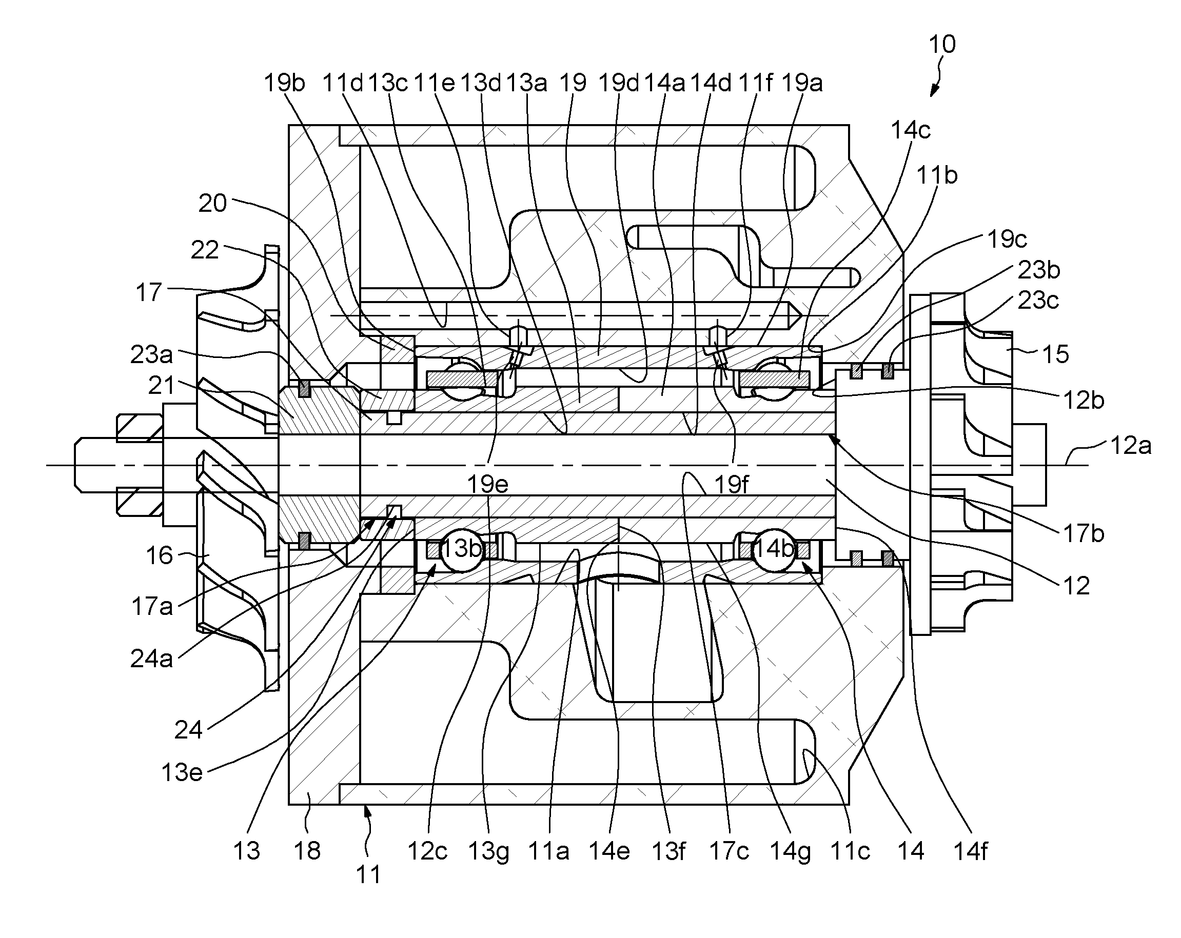
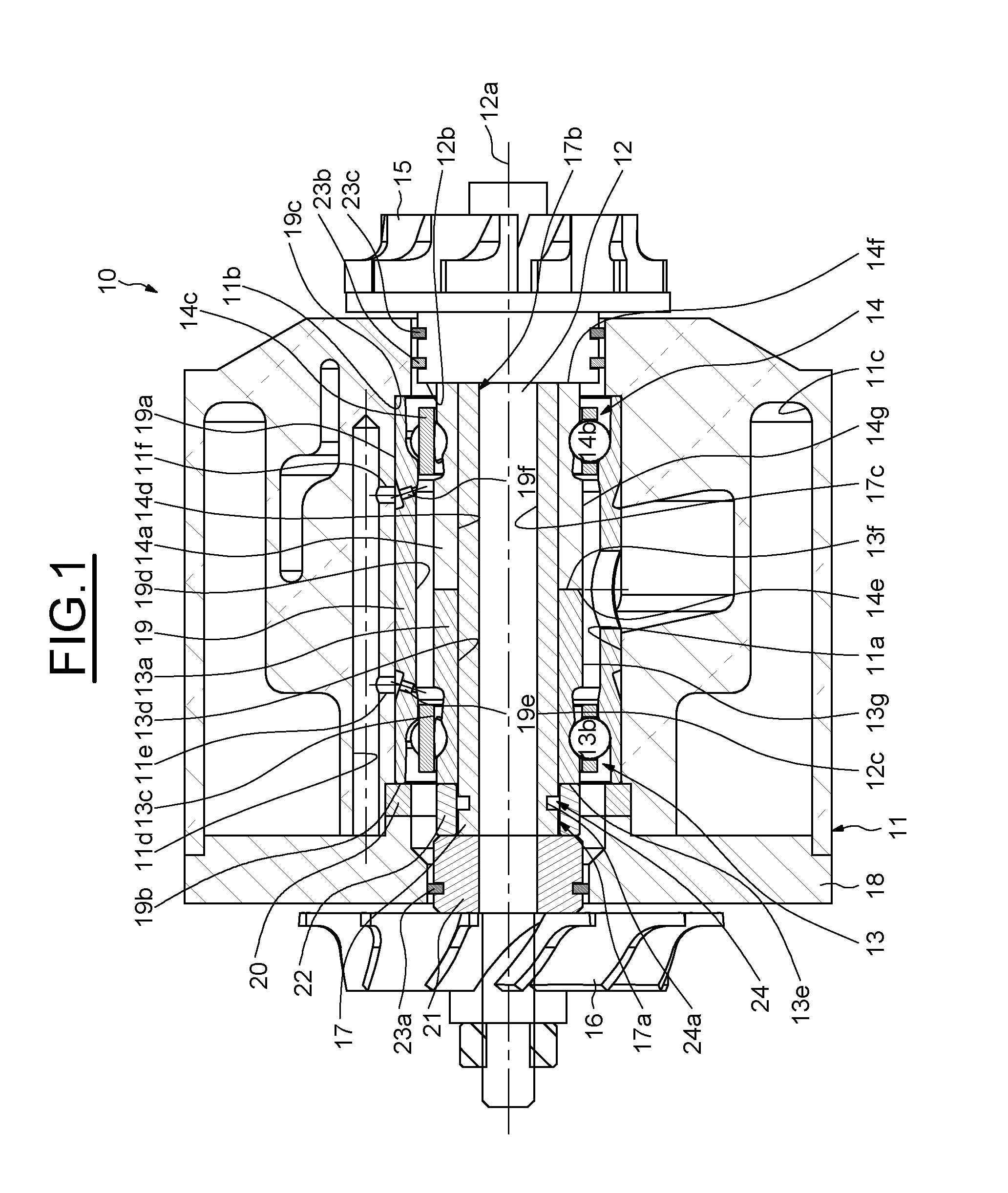
[0031]As illustrated on FIG. 1, which illustrates an embodiment of a turbocharger 10 according to an example of the invention, the turbocharger 10 comprises a housing 11, a shaft 12 extending along an axial axis 12a through a cylindrical bore 11 a or opening of the housing 11, two rolling bearings 13, 14 disposed into the bore 11a, a turbine wheel 15 fixed at one end of the shaft 12, a compressor wheel 16 fixed at an opposite end of said shaft 12, and an intermediate sleeve 17 radially located between the shaft 12 and the rolling bearings 13, 14. The turbocharger 10 also comprises a cap 18 fixed at an axial end of the housing 11.

[0032]Each rolling bearing 13, 14 comprises an inner ring 13a, 14a and an outer ring 19 between which is housed two rows of rolling elements 13b, 14b, which in this case are balls, two annular cages 13c, 14c maintaining the circumferential spacing of the rolling elements 13b, 14b. The axis of each rolling bearing 13, 14 is coaxial with the axis 12a of the sh...


PUM


Abstract

Turbocharger comprising a shaft, a housing, a turbine wheel and a compressor wheel mounted onto the shaft, at least one rolling bearing located between the shaft and the housing and comprising an inner ring, an outer ring and at least one row of rolling elements between raceways provided on the rings.Said turbocharger comprises at least one intermediate sleeve radially located between the shaft and the inner ring of the rolling bearing.

Description

CROSS-REFERENCE TO RELATED APPLICATION[0001]This United States Non-Provisional Utility application claims the benefit of priority to copending European Patent Application No. 11306085.9, filed on Aug. 30, 2011, which is incorporated herein in its entirety.FIELD OF THE INVENTION[0002]The present invention relates to the field of turbochargers, and in particular those used in combustion engines for automotive vehicles.BACKGROUND OF THE INVENTION[0003]In such application, a turbocharger is used to enhance the combustion engine performance by blowing compressed air into the cylinders of said engine.[0004]A turbocharger generally comprises a housing, a shaft extending through an opening formed on the housing, a turbine wheel mounted on a first end portion of the shaft and located in an exhaust gases passage of the combustion engine, a compressor wheel mounted on an opposite second end portion of said shaft and located in an admission gases passage of the engine, and rolling bearings disp...

Claims


Application Information

Patent Timeline
Patent Type & Authority Applications(United States)
IPC IPC(8): F04D29/059
CPCF01D25/16F04D29/059F05D2240/50F02C6/12F16C35/073F16C19/184F16C2360/24
Inventor BERRUET, NICOLASCHAMBONNEAU, CHARLESCORBETT, RICHARDGHILBERT-SIMON, AURELIENLIVERATO, YVES-ANDRERIBAULT, PATRICEVIAULT, SAMUEL
Owner AB SKF
Learn More