UV Laser Exposure Of Housings And Components Of Door Drives And Door Closers

a technology of laser exposure and door drive, which is applied in the direction of wing accessories, heat treatment equipment, furniture, etc., can solve the problems of affecting the functioning generating noises that might be considered disturbing, and abrasion, so as to achieve the effect of reducing the abrasion of the door operator or the door closer during actuation, increasing the wear resistance of the door operator or the door closer, and increasing the wear resistan

a technology of laser exposure and door drive, which is applied in the direction of wing accessories, heat treatment equipment, furniture, etc., can solve the problems of affecting the functioning generating noises that might be considered disturbing, and abrasion, so as to achieve the effect of reducing the abrasion of the door operator or the door closer during actuation, increasing the wear resistance of the door operator or the door closer, and increasing the wear resistan

US20130227815A1Inactive Publication Date: 2013-09-05DORMA GMBH & CO KG

Image

  • UV Laser Exposure Of Housings And Components Of Door Drives And Door Closers
  • UV Laser Exposure Of Housings And Components Of Door Drives And Door Closers
  • UV Laser Exposure Of Housings And Components Of Door Drives And Door Closers

Examples


Embodiment Construction

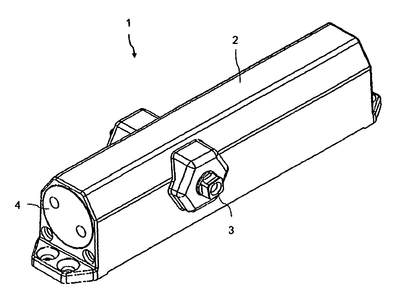
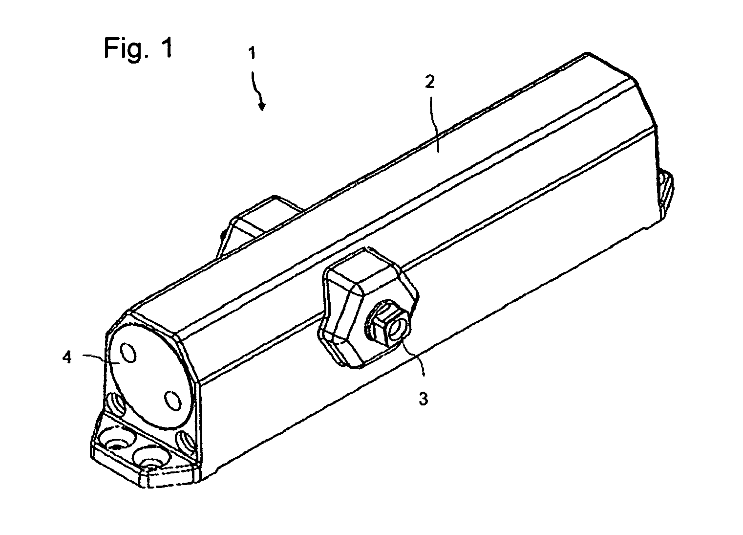
[0018]A diagrammatic perspective view of an embodiment of an inventive door closer 1 is shown in FIG. 1. In this case, the mechanical components of the door closer 1 are surrounded by a housing 2. The inside of the housing 2 is accessible through a screwable terminal plate 4. Inside the door closer 1, the mechanical components are actuated by a shaft 3. A piston 7 (FIG. 3) is retained in a movable manner in a reception 5 (FIG. 2) of the housing 2 and is driven via the shaft 3. On account of the inventive treatment of surfaces 6, 8 of the reception 5 and the piston 7, the friction between these structural components of the door closer 1 is reduced. The high wear resistance and the life span of the door closer 1 can be thus increased.

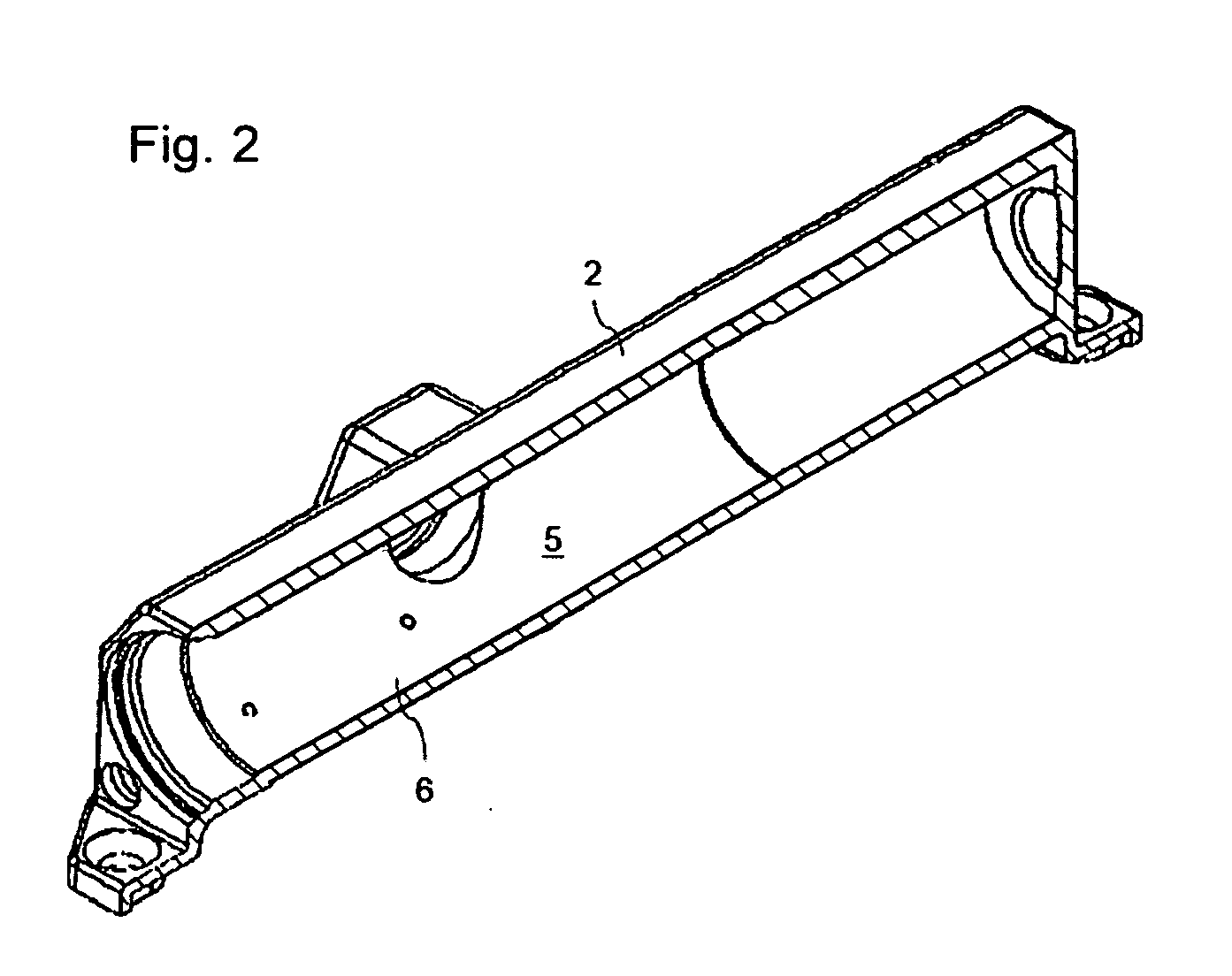
[0019]FIG. 2 is a diagrammatic perspective sectional view of the housing 2 of the inventive door closer 1 of FIG. 1. Other structural components are not illustrated. The internal circumferential surface 6 of the reception 5 is clearly visible. The inventi...


PUM

PropertyMeasurementUnit
Depthaaaaaaaaaa
Depthaaaaaaaaaa
Strengthaaaaaaaaaa

Abstract

A door operator or a door closer having at least one housing and at least one piston supported to be movable in a reception of the housing. The surfaces of the reception and / or of the at least one piston have been treated by exposure to electromagnetic radiation.

Description

CROSS REFERENCE TO RELATED APPLICATIONS[0001]This is a U.S. national stage of application No. PCT / EP2011 / 005356 , filed on 25 Oct. 2011. Priority is claimed on German, Application No.: 10 2010 060 385.6, filed 5 Nov. 2010, the content of which is incorporated here by reference.BACKGROUND OF THE INVENTION[0002]1. Field of the Invention[0003]The present invention relates to a door operator or to a door closer, wherein the door operator or the door closer includes at least one housing, a reception, and at least one piston, which is supported to be movable in said reception.[0004]2. Description of Prior Art[0005]A door operator is a device for automatically opening and closing a door. The door may be for example a swing leaf door or a sliding door. A door closer, however, is only utilized for automatically closing a door. In this case, the door operator or the door closer effects in particular the movement of a door leaf into a casing or in relation to a casing. It is known to execute a...

Claims


Application Information

Patent Timeline
05 Sep 2013
Publication
US20130227815A1
IPC
E05F1/00
CPC
C21D1/06; C21D1/09; C21D1/10; C21D9/14; E05F3/10; E05Y2201/454; Y10T16/56; E05Y2800/43
Inventors
WULBRANDT, TIM