
Gas turbine engine configured to shape power output

a technology of gas turbine engine and power output, which is applied in the direction of engines, machines/engines, mechanical equipment, etc., can solve the problems of large reduction in compressor efficiency and sharp drop in power with further increases, so as to reduce the power output of parts, reduce the mass flow of air, and reduce the effect of mass flow

Active Publication Date: 2013-09-05
SIEMENS ENERGY GLOBAL GMBH & CO KG
View PDF8 Cites 33 Cited by
  • Summary
  • Abstract
  • Description
  • Claims
  • Application Information

AI Technical Summary

Benefits of technology

The patent text describes how the position of IGVs (IGVs) affects the output of gas turbine engines. Opening the IGVs from their predetermined position increases the power output of the engine, while closing them reduces the mass flow of air into the compressor, resulting in a lower power output. The technical effect of this patent is to provide a method for controlling the power output of gas turbine engines by adjusting the position of the IGVs.

Problems solved by technology

However, once the maximum efficiency is reached, it drops sharply with further increases in power.
This drop is due to aerodynamic losses that occur in the turbine when there is flow beyond the optimum design for a row of airfoils.
When only one row is used, large mass flow reductions result in large reductions in compressor efficiency.

Method used


Image

  • Gas turbine engine configured to shape power output
  • Gas turbine engine configured to shape power output
  • Gas turbine engine configured to shape power output

Examples


Embodiment Construction

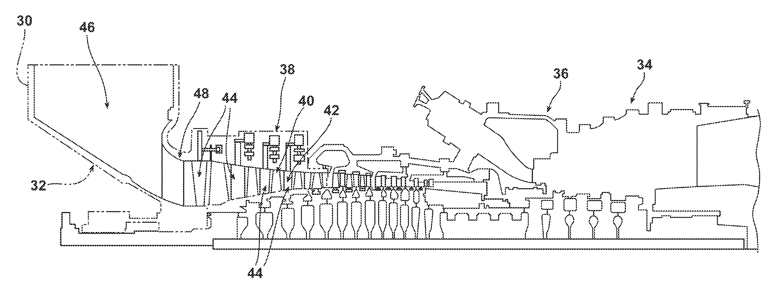
[0044]In the following detailed description of the preferred embodiment, reference is made to the accompanying drawings that form a part hereof, and in which is shown by way of illustration, and not by way of limitation, a specific preferred embodiment in which the invention may be practiced. It is to be understood that other embodiments may be utilized and that changes may be made without departing from the spirit and scope of the present invention.

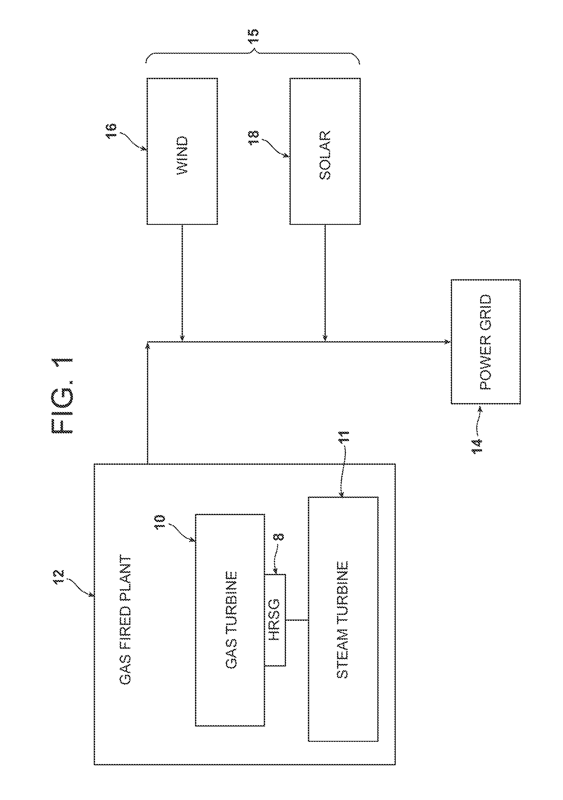
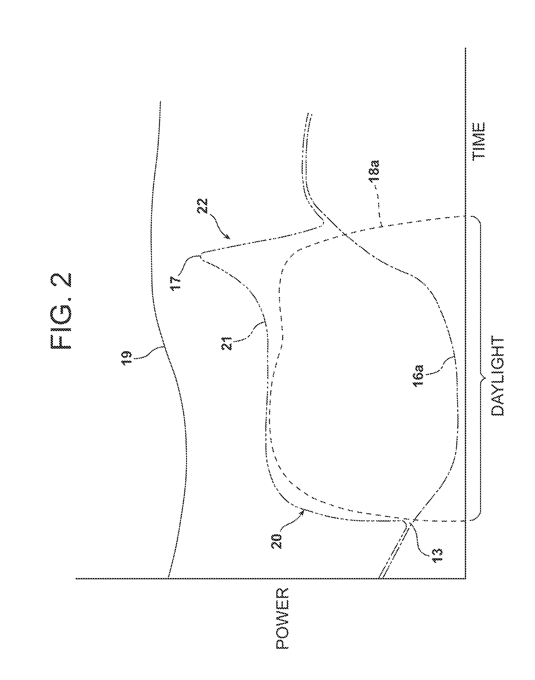
[0045]The present invention relates to a gas turbine engine and method of controlling the gas turbine engine in relation to a power grid having a plurality of additional power generation sources. In particular, the power grid may include one or more renewable energy sources, such as a wind power source and a solar power source. In addition, it may be expected that the power grid includes a plurality of other contributing power sources that may include, but is not necessarily limited to, one or more nuclear, coal, and gas turbine based po...


PUM


Abstract

A gas turbine engine and method of controlling the gas turbine engine that may be utilized in a power grid having a plurality of additional power generation sources. The gas turbine engine is configured with a compressor having an enlarged mass flow volume. The gas turbine engine may be operated at a base load for supplying power to the power grid at a part load and optimum efficiency for the engine, and may be ramped up to a higher output to supply a peak load output to the power grid.

Description

CROSS REFERENCE TO RELATED APPLICATION[0001]This application claims the benefit of U.S. Provisional Patent Application Ser. No. 61 / 606,537, filed Mar. 5, 2012, entitled “GAS TURBINE ENGINE CONFIGURED TO SHAPE POWER OUTPUT”, the entire disclosure of which is incorporated by reference herein.FIELD OF THE INVENTION[0002]This invention relates to a gas turbine engine and, more particularly, to a gas turbine engine for producing power in base load and peaking power on a power grid.BACKGROUND OF THE INVENTION[0003]Gas turbines have been in use for electric power production for decades. Over that time, the industry has changed significantly and this has driven a change in the desired attributes and capabilities for gas turbines used for power production. In the 1980's and early 1990's, gas turbines were primarily used in base load operation. Since that time operational requirements have changed and gas turbines are used to load follow, changing operating load frequently over time. This req...

Claims


Application Information

Patent Timeline
IPC IPC(8): F02C9/20
CPCF05D2270/05F05D2270/20F02C7/057F02C9/28F02C9/54F02C9/20
Inventor MARINI, BONNIE D.BOHINSKY, BRIAN J.
Owner SIEMENS ENERGY GLOBAL GMBH & CO KG
Learn More