Device for the light stimulation and cryopreservation of biological samples

a technology for biological samples and devices, applied in lighting and heating devices, domestic cooling devices, instruments, etc., can solve the problems of inability to irradiate samples, inability to use fill liquid, and large amount of time required to load samples, so as to facilitate the reliable preservation of photostimulated state, facilitate the cooling process, and stable in position

Active Publication Date: 2013-09-05
LEICA MICROSYSTEMS GMBH
View PDF12 Cites 17 Cited by
  • Summary
  • Abstract
  • Description
  • Claims
  • Application Information

AI Technical Summary

Benefits of technology

[0014]Further it may be advantageous when the high-pressure chamber is provided with a sample holder made of a material which is transparent to the light supplied to the high-pressure chamber from the outside. In this case, the sample holder (sample cartridge) may have a sample carrier and at least one transparent shell piece, wherein the sample carrier has an opening for receiving the sample. Moreover, the at least one shell piece may be provided with a channel for a cooling medium, wherein the sample carrier is enclosed in the mounted sample holder by the at least one shell piece, and the channel of the at least one shell piece leads from an external orifice to the area of the opening in the sample carrier. This allows the sample to be photostimulated and then cryopreserved in the same position in the sample holder, thereby facilitating the reliable preservation of the photostimulated state. Placing the sample in the sample cartridge keeps it stable in position throughout the entir

Problems solved by technology

However, use of the fill liquid is not mandatory, especially since various types of samples should not come into contact with alcohol.
However, under normal conditions (i.e., under the normal living conditions of the biological parent material, generally at ambient temperature and pressure) the photostimulated state is short-lived, and therefore, additional measures are required to fix the transient stimulated state of the sample.
With known high-pressure freezing devices, however, irradiation of the sample is possible only outside of the high-pres

Method used


Image

  • Device for the light stimulation and cryopreservation of biological samples
  • Device for the light stimulation and cryopreservation of biological samples
  • Device for the light stimulation and cryopreservation of biological samples

Examples


Embodiment Construction

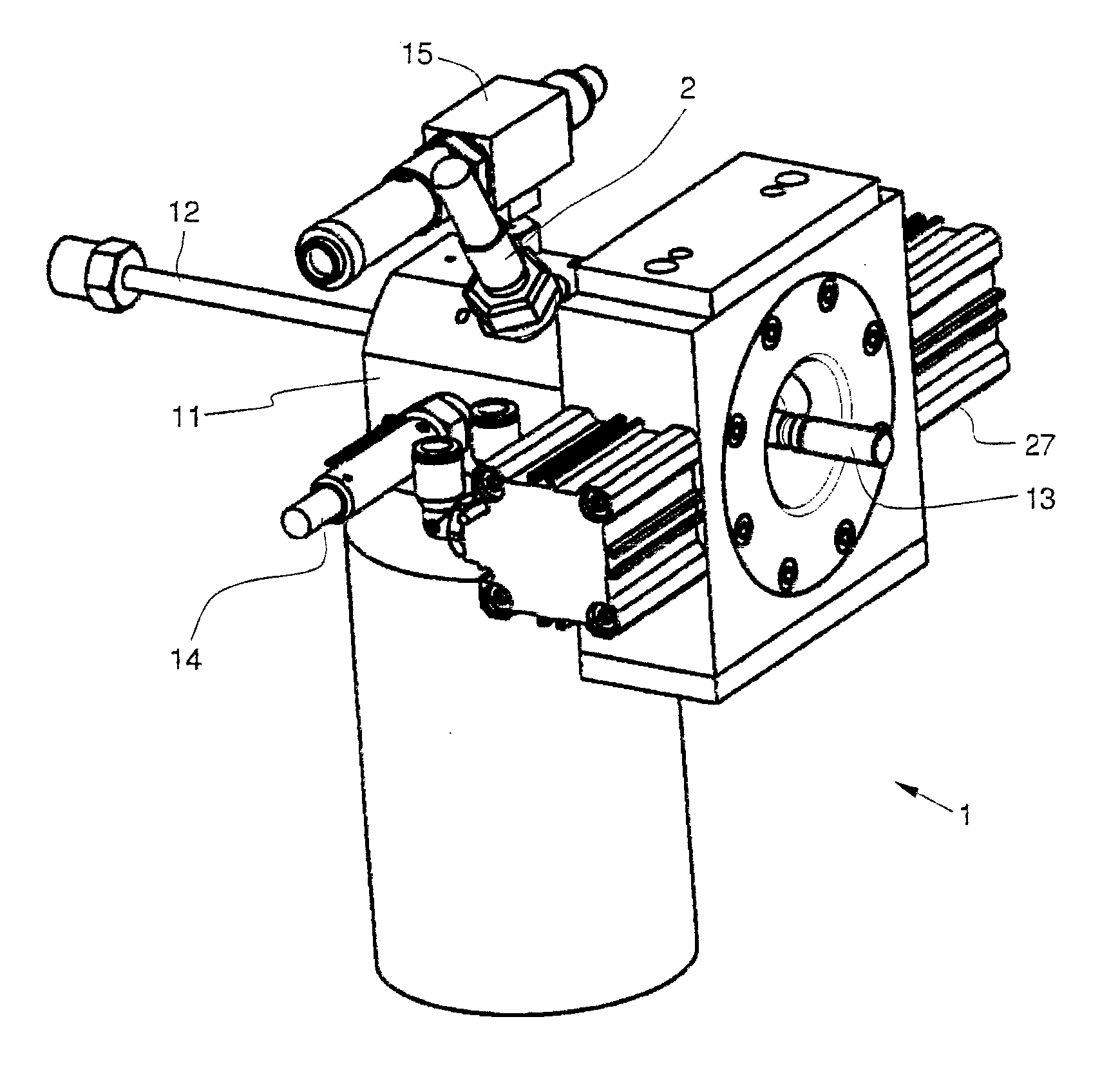
[0030]The exemplary embodiment relates to a high-pressure freezing system, which is based upon the layout of the “Leica EM HPM100” and represents a development thereof. The principal structure of the high-pressure freezing system, which was described above in reference to FIG. 8, is also used in the device of the exemplary embodiment. It should be emphasized, however, that the invention is not limited to this exemplary embodiment or to high-pressure freezing systems such as those based upon the stated Leica device, but also includes other implementations of the stimulation / preservation process based on the inventive concept as defined in the claims.

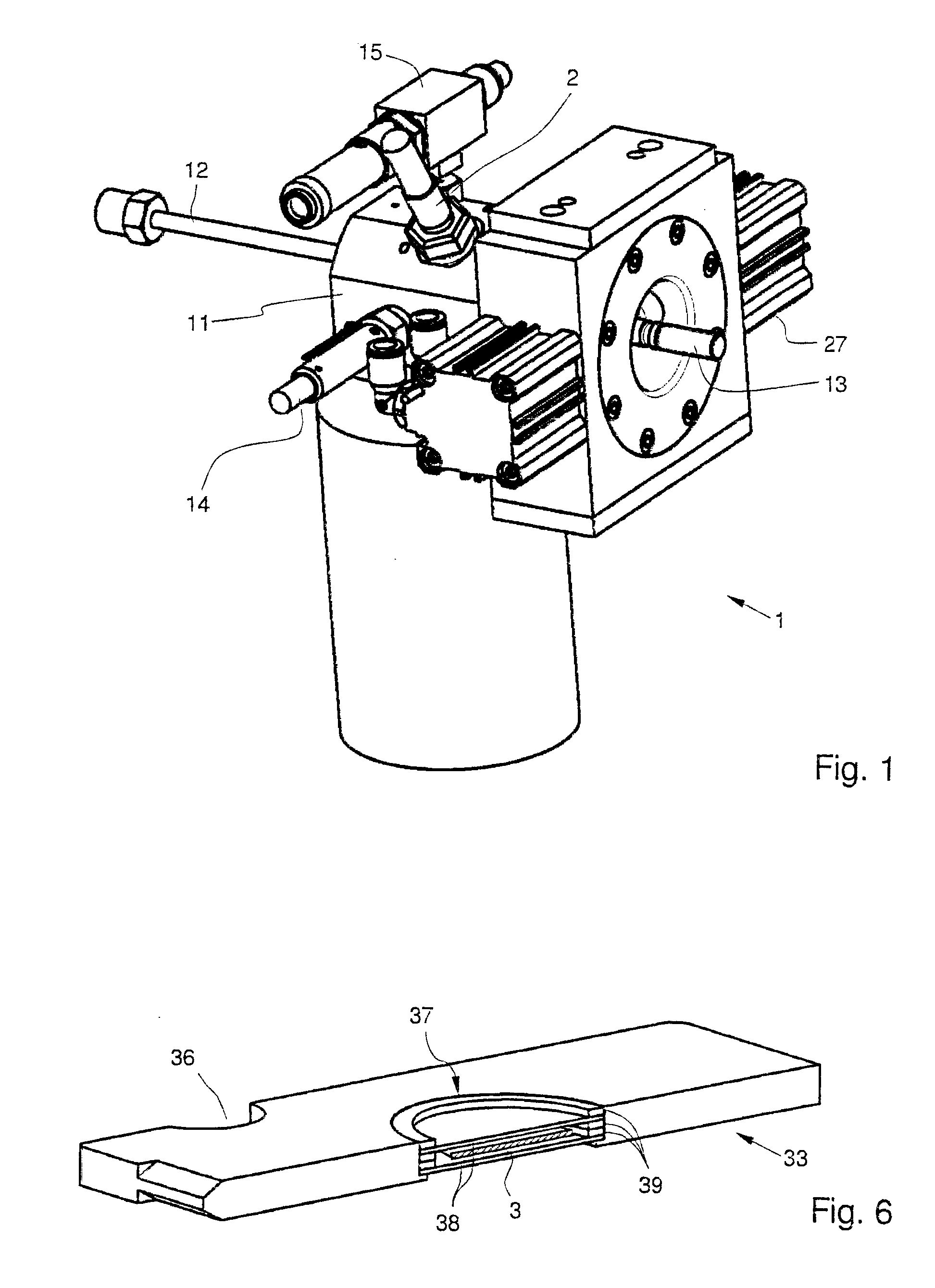
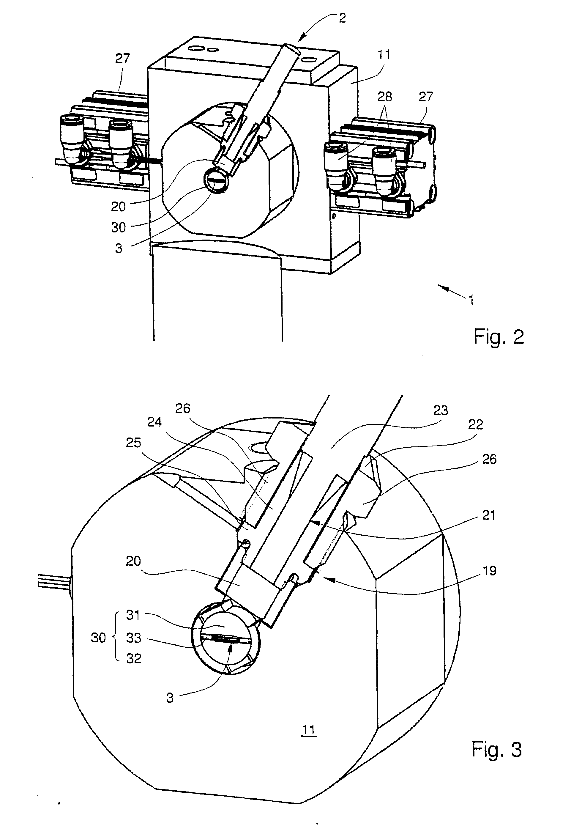
[0031]FIG. 1 shows the entire high-pressure freezing system 1 according to the exemplary embodiment, in a perspective view. A high-pressure chamber 11 of the known type has a high-pressure line 12 for a cryogen, in this case liquid nitrogen (LN2), and a holder 13 for a cartridge (FIGS. 2 and 4). As is already known from the “Leica EM HPM1...


PUM

PropertyMeasurementUnit
Temperatureaaaaaaaaaa
Pressureaaaaaaaaaa
Electrical resistanceaaaaaaaaaa

Abstract

In a device (1) for rapid pressure-freezing an aqueous sample (3), such as a biological specimen, a pressurized cooling medium can be fed into a high-pressure chamber (11) into which a sample holder (30) containing a sample (3) is inserted and which is sealed with a pressure-tight seal, to the location of the sample holder (30) held therein. The high-pressure chamber (11) comprises a viewing window structure (2) with a pressure-tight window (20), through which light can be directed from the outside onto the sample (3) located in the sample holder (30). The window (20) can comprise a transparent window element made of a high-pressure-resistant material, wherein the window element (20) is held by a pressure- and temperature-resistant window bearing provided in the high-pressure chamber.

Description

CROSS REFERENCE TO RELATED APPLICATIONS[0001]This application claims priority of the Austrian patent application number A50051 / 2012 filed Mar. 2, 2012, the entire disclosure of which is incorporated by reference herein.FIELD OF THE INVENTION[0002]The invention relates to a device for rapidly freezing an aqueous sample, in particular a biological sample, under pressure, specifically using a high-pressure chamber into which a sample holder containing the sample can be inserted, and which can be sealed forming a pressure tight seal, wherein a cooling medium can be supplied to the high pressure chamber and fed to the site of the sample holder located therein. The invention further relates to a method of high-pressure freezing that is suitable for the device.BACKGROUND OF THE INVENTION[0003]A high-pressure freezing device of the above-stated type is described in DE 100 25 512 A1, in which additionally a particularly rapid pressure increase is achieved using a prestressed pneumatic cylind...

Claims


Application Information

Patent Timeline
IPC IPC(8): G01N1/42
CPCB29K2083/005B29C45/0053B29C2045/0075G21K7/00G01Q30/10G02B7/007G01N1/42
Inventor LIHL, REINHARDWOGRITSCH, RAINERPLANK, HEINZ
Owner LEICA MICROSYSTEMS GMBH
Why Eureka
Try Eureka