
Magnetic shield

Active Publication Date: 2013-09-05
APPLE INC
View PDF2 Cites 17 Cited by
  • Summary
  • Abstract
  • Description
  • Claims
  • Application Information

AI Technical Summary

Benefits of technology

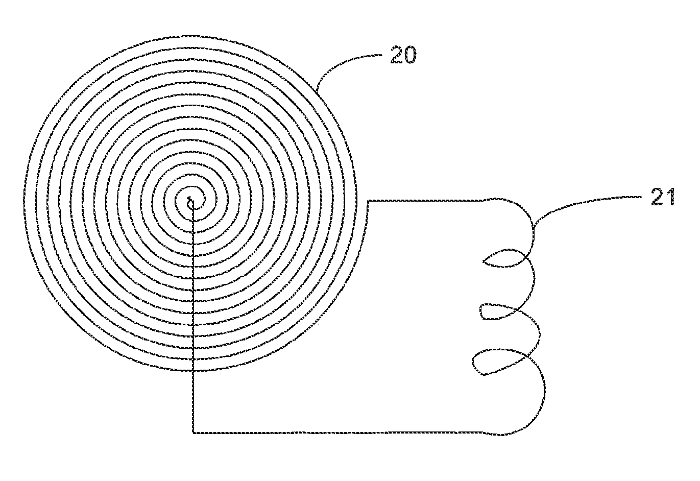
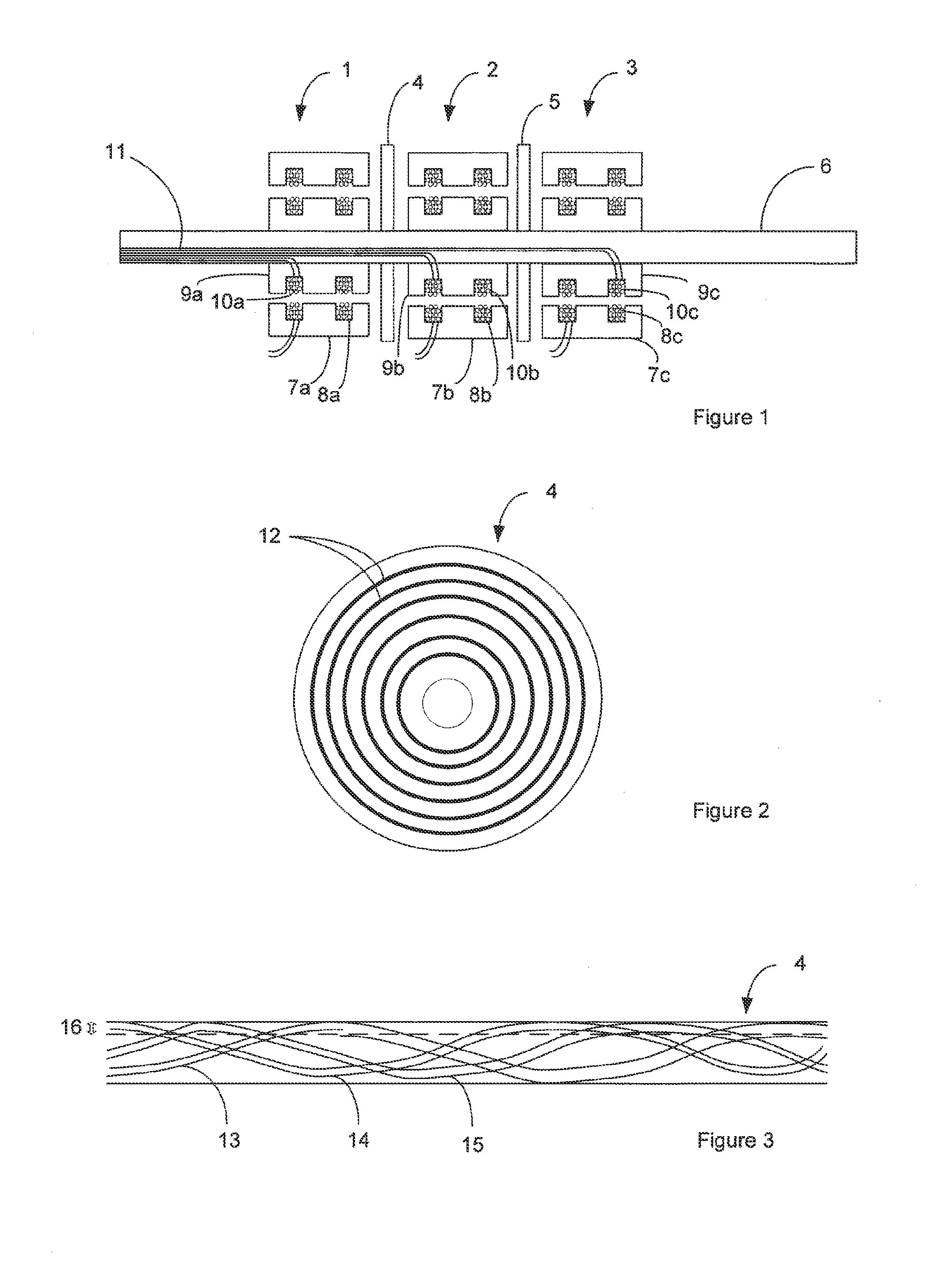
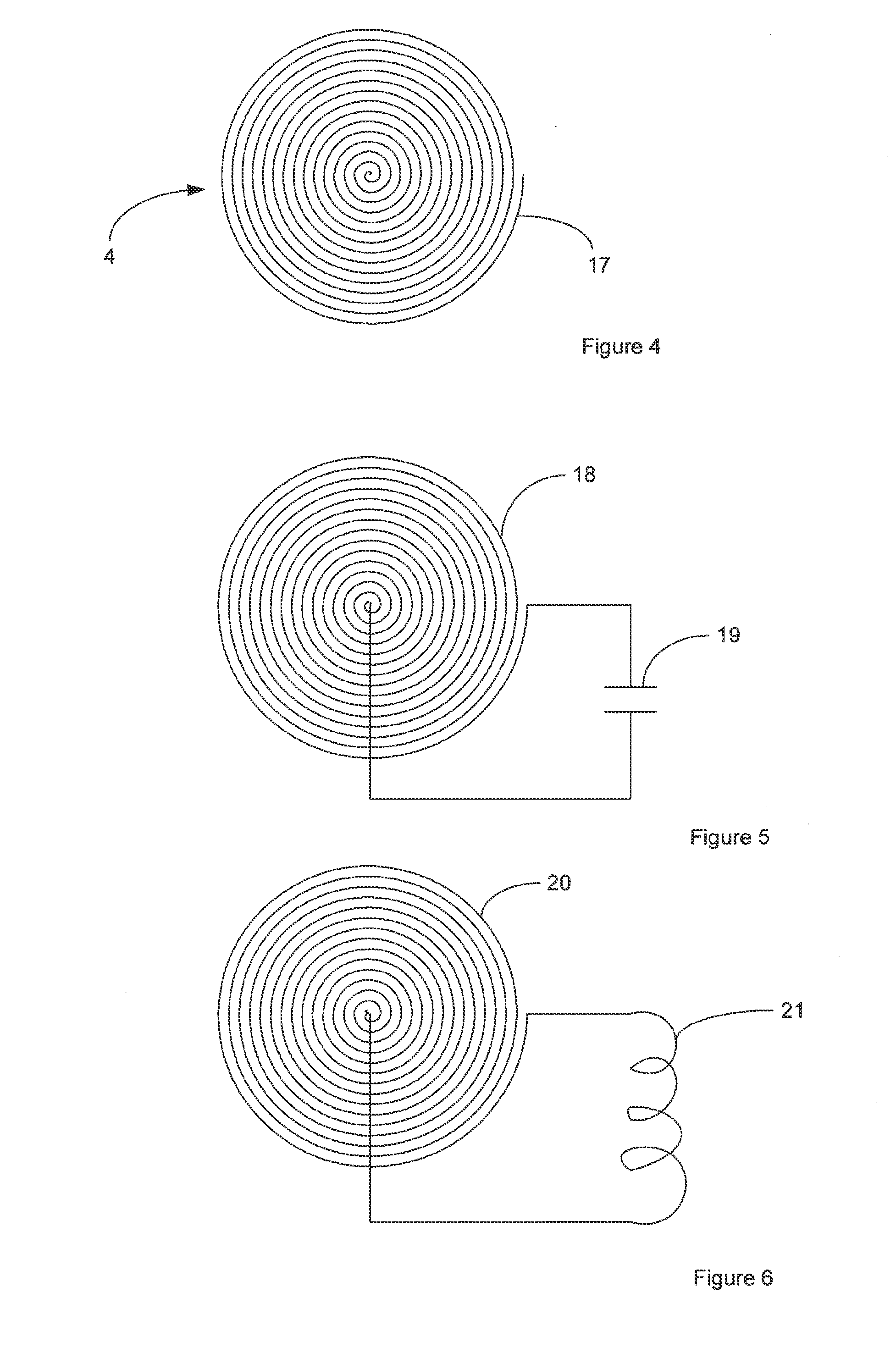
This patent is about how to make a strong shield to protect electric conductors from magnetic interference. The ideal shape of the shield is a circle or spiral, with a disc or curved sheet being the best choice. The more the conductor is shielded, the better the protection is. The conductor can be either capacitively or inductively loaded. In simple terms, this patent explains how to make a strong shield to protect electric conductors from magnetic interference.

Problems solved by technology

Firstly and most importantly, though a conductive plate shield may be physically thick, at ICPT frequencies, only the surface of the conductive plate will conduct current, due to the skin effect. This means that the effective resistance of the conductive sheet is much higher than would be measured at DC, so the resistive losses in the shield can be high.
Secondly, the regions of the solid conductive plate where the incident magnetic field is strongest will have higher losses than other areas with weaker incident magnetic fields. This is because the eddy currents are higher in the regions with high incident magnetic field.
Existing shields suffer from limited flexibility in that their degree of screening cannot be easily tailored to a specific requirement.

Method used


Image

  • Magnetic shield
  • Magnetic shield
  • Magnetic shield

Examples


Embodiment Construction

[0009]According to one exemplary embodiment there is provided an ICPT system including a transmitting coil and a receiving coil wherein at least one coil is at least partly shielded by a magnetic shield formed of one or more conductors wherein the shield has a surface which in use is exposed to an incident magnetic field wherein the one or more conductors undulate towards and away from the surface so as to distribute currents induced in portions of the one or more conductors at the surface of the shield to portions of the one or more conductors away from the surface of the shield.

[0010]Preferably the one or more conductors undulate from a depth within about one skin depth from the surface to greater than one skin depth below the surface. The one or more conductors are preferably elongate conductors arranged to distribute the eddy currents along a path length that is long with respect to the size of the shield.

[0011]The one or more conductors preferably have an average thickness of a...


PUM


Abstract

A magnetic shield for shielding adjacent coils of an ICPT system. One or more conductors are configured to distribute induced eddy currents from the surface of the shield to below the surface and thus reduce heating due to eddy currents.The magnetic shield may be employed to transfer power over rotary couplings, such as the shaft of a wind turbine.

Description

FIELD OF THE INVENTION[0001]This invention relates to a magnetic shield. More particularly but not exclusively the invention relates to a magnetic shield for shielding transmitting and receiving coil pairs of an inductively coupled power transfer (ICPT) system. It also relates to shields for shielding metallic objects in close proximity.BACKGROUND OF THE INVENTION[0002]In ICPT systems it is sometimes necessary to have transmitting and receiving coils in close proximity to other transmitting and receiving coils, to electrically conductive surfaces, or to sensitive electronics. For example, in the multiple power and data transmission channels commonly employed in wind turbines. It is desirable for each channel to be isolated from the adjacent channel. Conventionally this may be achieved using a conductive plate between channels. It may also be desirable to provide shielding to avoid losses due to surrounding metallic elements.[0003]Time-varying magnetic fields generate eddy currents i...

Claims


Application Information

Patent Timeline
IPC IPC(8): H05K9/00
CPCH05K9/00H05K9/0075H01F27/289H01F38/14H02J50/10H02J50/70H02J50/40H01F27/363H01F27/36H01F2027/348
Inventor ROBERTSON, DANIELBHARGAVA, KUNALMISHRIKI, FADYREN, SAINING SUNNY
Owner APPLE INC
Learn More