Valve timing control device of internal combustion engine

a timing control and internal combustion engine technology, applied in the direction of valve arrangements, machines/engines, mechanical equipment, etc., can solve the problems of reducing the cross sectional area and affecting the operation of the communication passage. , to achieve the effect of reducing the cross sectional area

Active Publication Date: 2013-09-12
HITACHI ASTEMO LTD
View PDF1 Cites 5 Cited by
  • Summary
  • Abstract
  • Description
  • Claims
  • Application Information

AI Technical Summary

Benefits of technology

[0006]It is therefore an object of the present invention to provide a valve timing control device of an internal combustion engine, which is free of the above-mentioned drawback.
[0007]That is, in accordance with the present invention, there is provided a valve timing control device of an internal combustion engine, which comprises an annular housing rotated by a crankshaft of the engine and having a plurality of shoes on a peripheral inner surface thereof, adjacent two of the shoes defining therebetween an operation chamber; a vane rotor connected to a camshaft of the engine to rotate therewith, the vane rotor being formed with vanes each dividing the operation chamber into an advancing operation chamber and a retarding operation chamber, the vane rotor being turned in an advancing or retarding direction relative to the annular housing when a hydraulic pressure is supplied to or discharged from the advancing and retarding operation chambers respectively; a first lock member provided by one of the vane rotor and the annular housing and movable toward and away from the other of the vane rotor and the annular housing with a driving force different from the hydraulic pressure supplied to the operation chambers; a second lock member provided by one of the vane rotor and the annular housing a...

Problems solved by technology

However, if, upon stopping of the engine, the lock pin fails to engage with the lock hole having advancing and retarding operation chambers kept filled with a certain amount of hydraulic fluid, immediate application of the alternating torque to the vane rotor does not induce a sufficient reciprocative swing movem...

Method used


Image

  • Valve timing control device of internal combustion engine
  • Valve timing control device of internal combustion engine
  • Valve timing control device of internal combustion engine

Examples


first embodiment

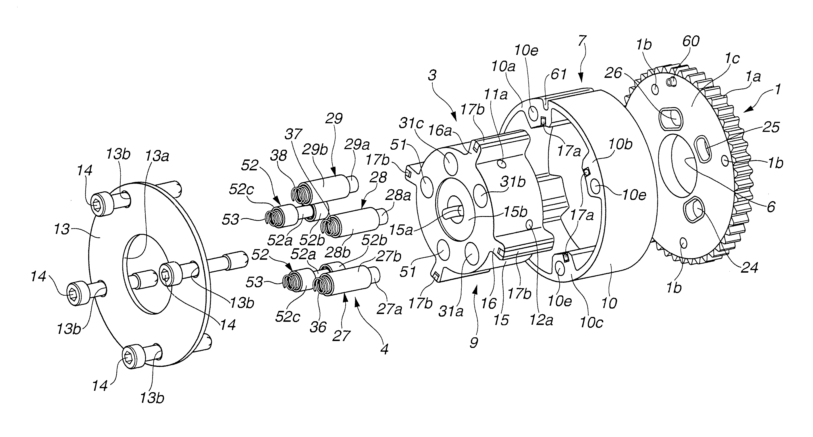
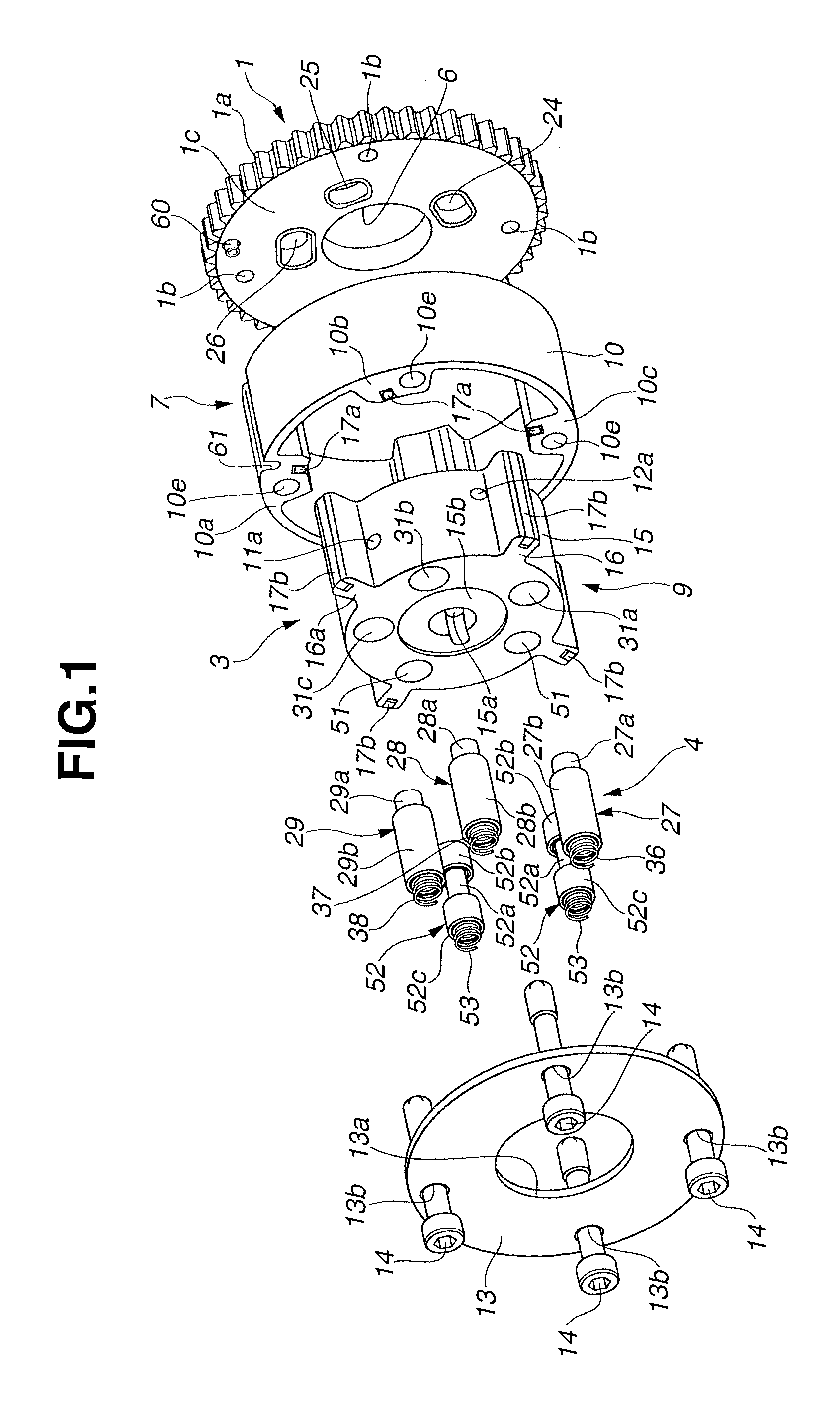
[0026]Referring to FIGS. 1 to 12, there is shown a valve timing control device of a first embodiment of the present invention.

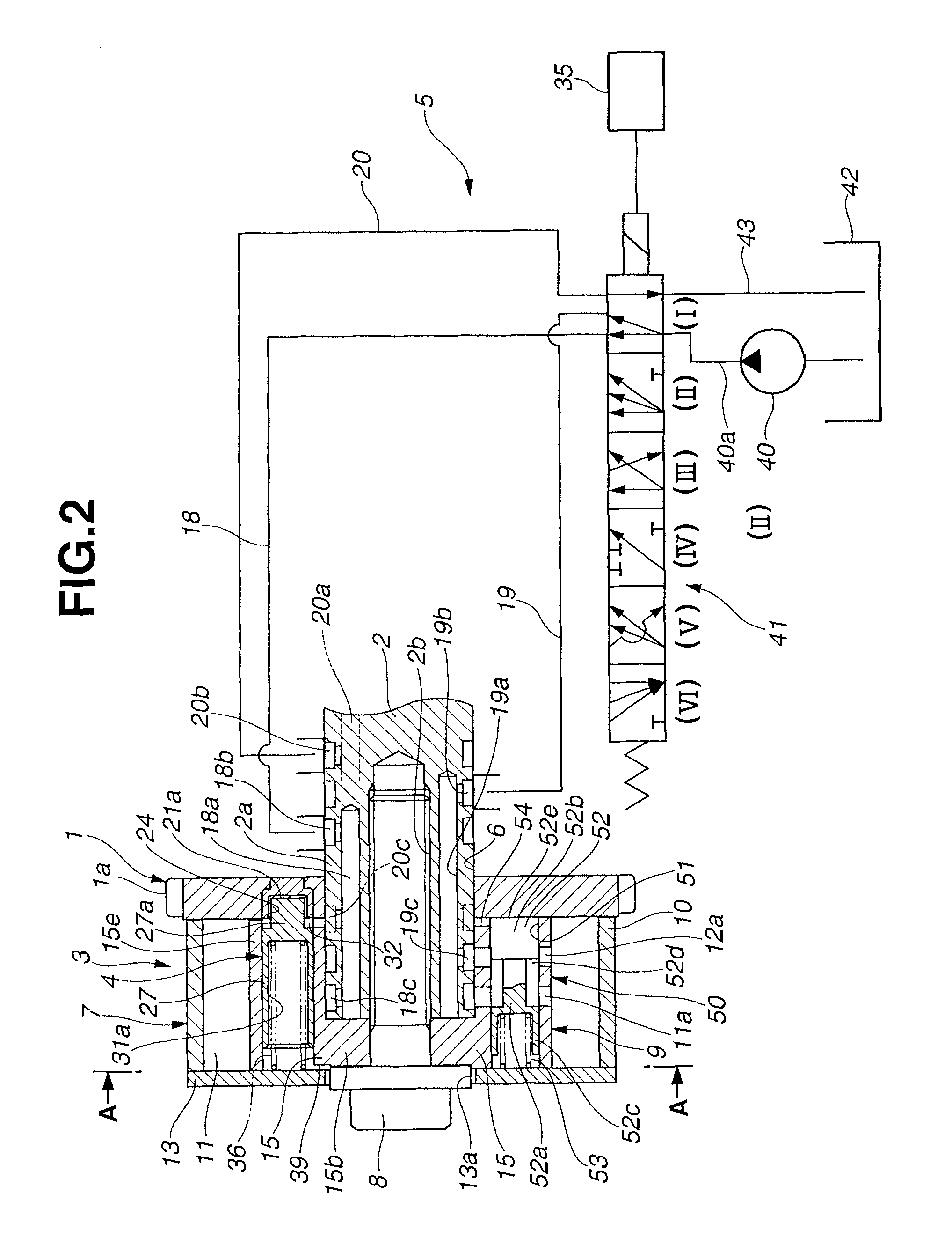
[0027]As is seen from FIGS. 1 to 4, particularly from FIG. 1, the valve timing control device of the first embodiment comprises a sprocket 1 that is driven by a crankshaft of an engine (viz., internal combustion engine) through a timing chain (not shown), an intake camshaft 2 (see FIGS. 2 and 4) that extends along a longitudinal axis of the engine and is rotatable relative to sprocket 1, a phase varying mechanism 3 that is arranged between sprocket 1 and intake camshaft 2 to vary a relative phase therebetween, a lock mechanism 4 that locks phase varying mechanism 3 at an intermediate angular position between the most advanced and retarded angular positions, and a hydraulic circuit 5 that feeds and drains a hydraulic pressure to and from phase varying mechanism 3 and lock mechanism 4 to independently operate the mechanisms 3 and 4.

[0028]As may be seen from FIG...

second embodiment

[0159]Referring to FIGS. 13A and 13B, there is shown a valve timing control device of a second embodiment of the present invention.

[0160]In this second embodiment, in place of passage control mechanism 50 used in the first embodiment, there is employed a passage control mechanism 50′.

[0161]Due to work of this passage control mechanism 50′, there can be produced a communication space “C” between a concave inside surface 10f of first shoe 10a of cylindrical body 10 and a convex outside surface 15c of rotor 15, as will be seen from FIG. 13B. Upon this, the neighboring retarding and advancing operation chambers 11 and 12 become communicated to each other through the space “C” produced.

[0162]As is seen from FIG. 13A, passage control mechanism 50′ comprises a rectangular groove 55 that is formed in first shoe 10a in a manner to face the convex outside surface 15c of rotor 15, a piston-like seal member 56 that is slidably received in rectangular groove 55 in a manner to selectively close a...


PUM


Abstract

Even if an internal combustion engine is stopped having a lock pin of a vane rotor kept disengaged from a lock recess, subsequent engine starting can instantly move the vane rotor to a desired angular position where the lock member an be engaged with the lock recess. The vane rotor has therein two passage control mechanisms each having a hydraulically actuated valve body. When the valve body is moved to a given position, retarding and advancing hydraulic holes become communicated to each other through an annular groove of the valve body. Due to this ON communication, retarding and advancing operation chambers become communicated, so that reciprocative swing movement of the vane rotor induced by an alternating torque produced at the starting of the engine is effectively made and thus the vane rotor can be quickly turned to the desired angular position for ease of engine starting.

Description

BACKGROUND OF THE INVENTION[0001]1. Field of the Invention[0002]The present invention relates in general a valve timing control device of an internal combustion engine, which controls an OPEN / CLOSE timing of intake and / or exhaust valves in accordance with an operation condition of the engine.[0003]2. Description of Related Art Japanese Laid-open Patent Application (Tokkai) 2003-222010 shows a vane-type valve timing control device which, at the time of stopping the internal combustion engine, locks a vane rotor to a given angular position between the most retarded angular position and the most advanced angular position by using a lock pin engageable with a lock hole.[0004]That is, in the device of the above publication, when the engine is stopped, the vane rotor is enforcedly turned, while repeating a reciprocative swing movement, to the given angular position by the power of a positive / negative alternating torque produced by valve springs and locked at the given angular position due...

Claims


Application Information

Patent Timeline
IPC IPC(8): F01L1/34
CPCF01L1/3442F01L2001/3443F01L2001/34423F01L2001/34466F01L2001/34459
Inventor WATANABE, ATSUSHITAKADA, YASUHIDEFUJITA, OSAMUSHIBUKAWA, TETSUYA
Owner HITACHI ASTEMO LTD
Why Eureka
Try Eureka