Multi-Stage Non-Pneumatic Resilient Wheel

a resilient wheel and multi-stage technology, applied in the field of laminated products, can solve the problems of reducing the impact resistance of the rolling wheel, so as to achieve the effect of increasing the impact resistance on the ground

Inactive Publication Date: 2013-09-12
MICHELIN & CO CIE GEN DES ESTAB MICHELIN +1
View PDF7 Cites 30 Cited by
  • Summary
  • Abstract
  • Description
  • Claims
  • Application Information

AI Technical Summary

Benefits of technology

[0038]Owing to these features, the wheel according to the invention makes it possible to increase the print on the ground without modifying the print on the ground generated by the shear band, by creating a new contact surface capable of distributing, over a greater surface area, the forces concentrated in the contact area generated by the shear band.
[0039]According to one advantageous embodiment, this effect is obtained in a continuous manner by adding a third flexible, but inextensible, membrane outside of those forming the shear band, and that is attached to the resilient wheel by spokes that are preferably very flexible in compression, but rigid in extension.

Problems solved by technology

However, such a rubber shear band is not without drawbacks.
Firstly, at the customary operating temperatures, for example between −30° C. and +40° C., it is relatively hysteretic, that is to say that some of the energy supplied for rolling is dissipated (lost) in the form of heat.
Next, for significantly lower operating temperatures, such as those that can be found, for example in geographical areas of polar type, or on the moon, typically below −50° C. or even less, it is well known that rubber rapidly becomes brittle, frangible and therefore unusable.
Under such extreme conditions, it is moreover understood that temperature fluctuations that are more or less sizable and rapid, combined, for example, with relatively high mechanical stresses, could also lead to adhesion problems between the two membranes and the shear layer, with a risk of localized buckling of the shear band level with the membranes and endurance that is in the end degraded.
However, during use on loose or sandy ground, this wheel is capable of causing sinking problems.
In such cases, losses of efficiency are observed in the traction exerted by the wheel.

Method used


Image

  • Multi-Stage Non-Pneumatic Resilient Wheel
  • Multi-Stage Non-Pneumatic Resilient Wheel
  • Multi-Stage Non-Pneumatic Resilient Wheel

Examples


Embodiment Construction

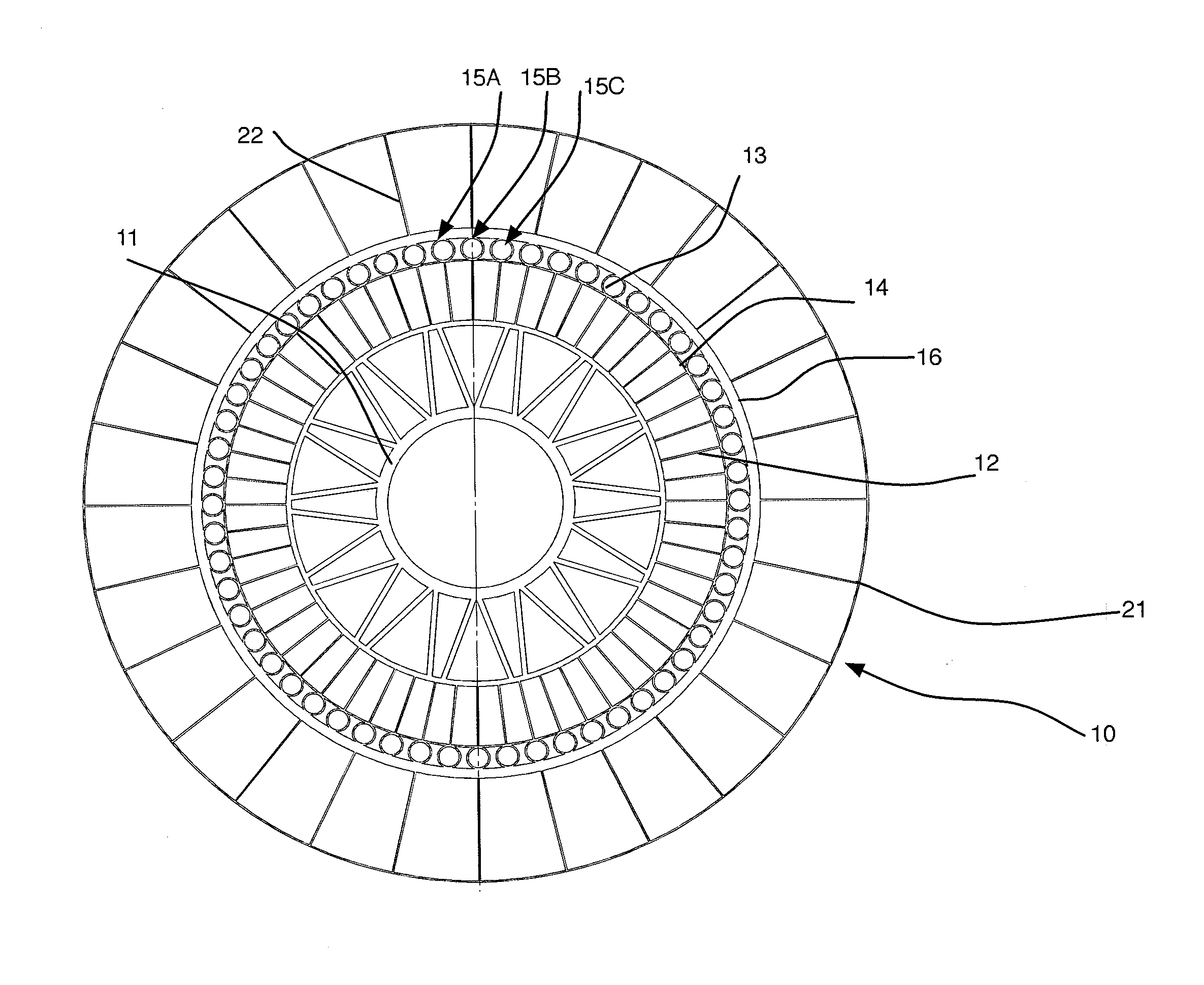
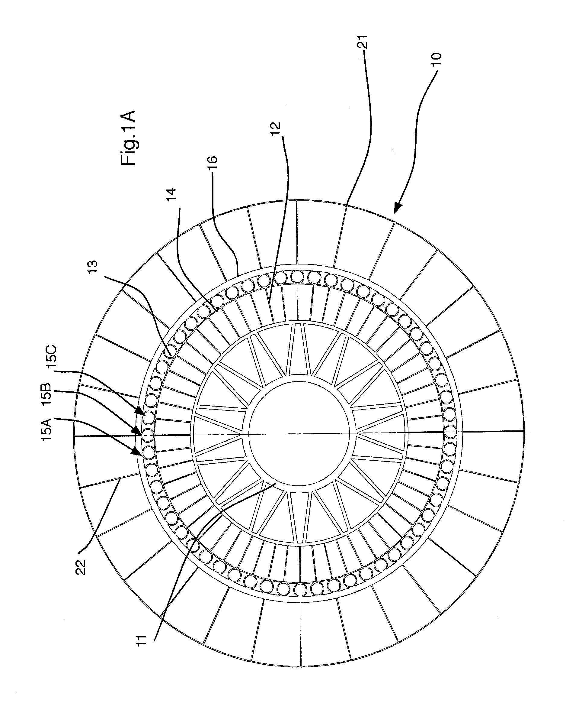
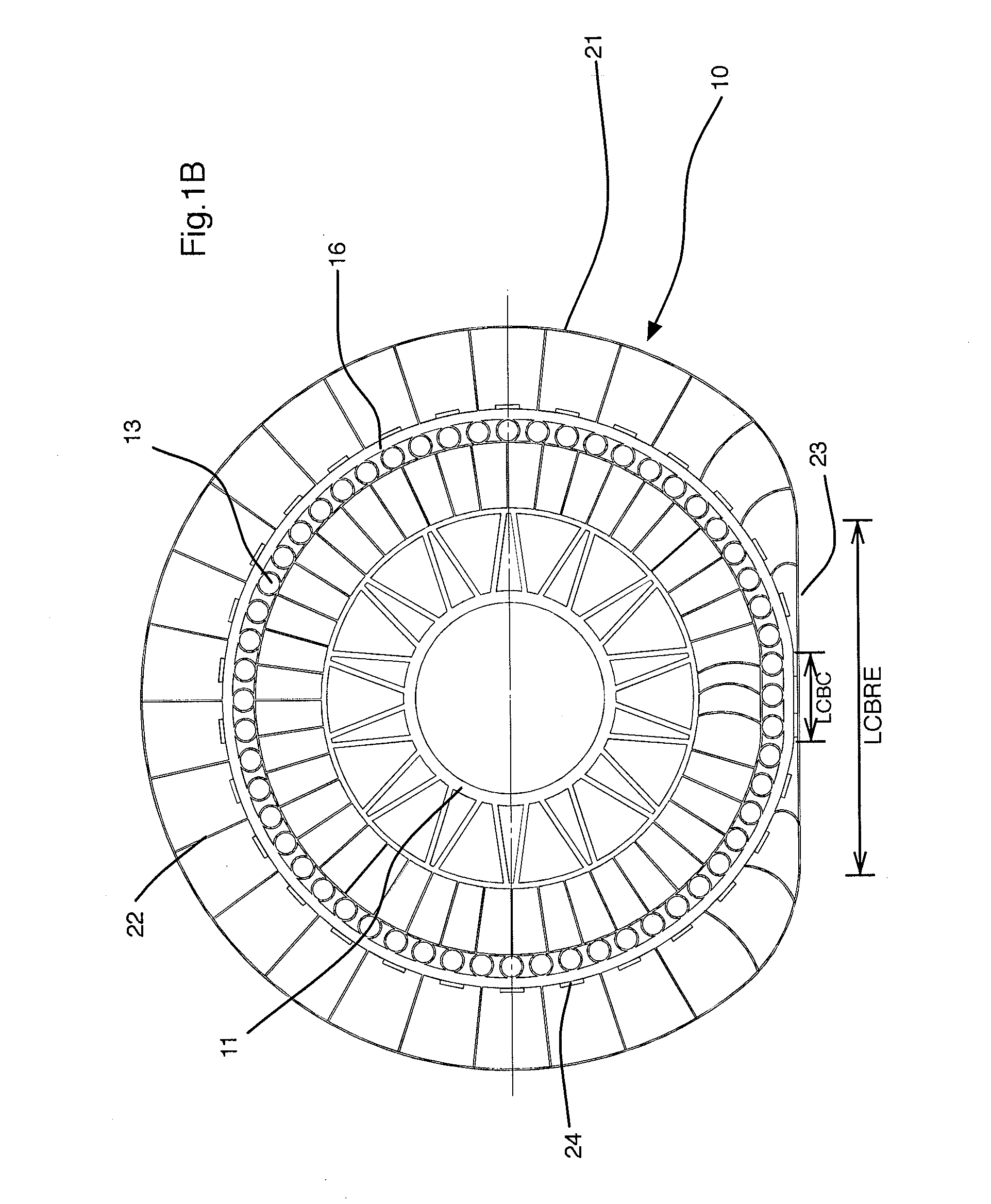
[0062]By way of example, FIG. 1C represents, very schematically, a radial cross section (i.e. in a plane perpendicular to the axis of rotation Y of the wheel) of the inner portion of a non-pneumatic resilient wheel (10) that is structurally supported (i.e. owing to a load-bearing structure), the circumferential shear band (13) of which is constituted by a laminated product.

[0063]This wheel defines three perpendicular directions, circumferential (X), axial (Y) and radial (Z), and comprises at least:[0064]a hub (11);[0065]an annular band referred to as a shear band (13) comprising at least one inner circumferential membrane (14) and one outer circumferential membrane (16) that are oriented in the circumferential direction X; and[0066]a plurality of support elements (12) or “wheel spokes” that connect the hub (11) to the inner circumferential membrane (14).

[0067]According to one advantageous embodiment,[0068]the two membranes (14, 16) are connected to one another, in zones (17) referre...


PUM


Abstract

Non-pneumatic resilient wheel (10), that is supported structurally and defines three perpendicular directions, circumferential (X), axial (Y) and radial (Z), this wheel comprising at least: a hub (11); an annular band referred to as a shear band (13) comprising at least one inner circumferential membrane (14) and one outer circumferential membrane (16) that are oriented in the circumferential direction X; and a plurality of support elements (12) that connect the hub (11) to the inner circumferential membrane (14), the wheel furthermore comprising: a flexible, circumferential contact membrane (21) oriented in the circumferential direction (X); a plurality of connecting elements (22) providing a connecting link between the circumferential contact membrane (21) and the annular shear band (13).

Description

FIELD OF THE INVENTION[0001]The present invention relates to laminated products, that is to say to products made of several layers or bands of planar or non-planar form, which are joined together, for example of the cellular or honeycomb type.[0002]The invention relates more particularly to resilient (flexible) wheels for motor vehicles of the “non-pneumatic” type: that is to say that do not require inflation gases such as air in order to assume their usable form, and to the incorporation in such wheels of laminated products, in particular when these laminated products are composite products, all or part of which is constituted of fibres coated in a resin matrix.[0003]The invention relates most particularly to a resilient wheel for a vehicle intended for use in extreme conditions, in particular at very low temperatures and on loose or sandy ground.PRIOR ART[0004]Non-pneumatic flexible wheels or tires are well known to a person skilled in the art. They have been described in a great ...

Claims


Application Information

Patent Timeline
Patent Type & Authority Applications(United States)
IPC IPC(8): B60B9/26
CPCB60B9/26B60B2900/111B60C7/14B60Y2200/11Y02T10/86
Inventor MERALDI, JEAN-PAULDELFINO, ANTONIO
Owner MICHELIN & CO CIE GEN DES ESTAB MICHELIN
Why Eureka
Try Eureka