
Rig fuel management systems and methods

a fuel management system and rig technology, applied in earth drilling, electrical equipment, dc source parallel operation, etc., can solve the problems of complex varying power requirements, inability to meet the needs of drilling rigs, so as to achieve efficient operation of rigs.

Active Publication Date: 2013-09-12
NABORS DRILLING TECH USA INC
View PDF12 Cites 22 Cited by
  • Summary
  • Abstract
  • Description
  • Claims
  • Application Information

AI Technical Summary

Benefits of technology

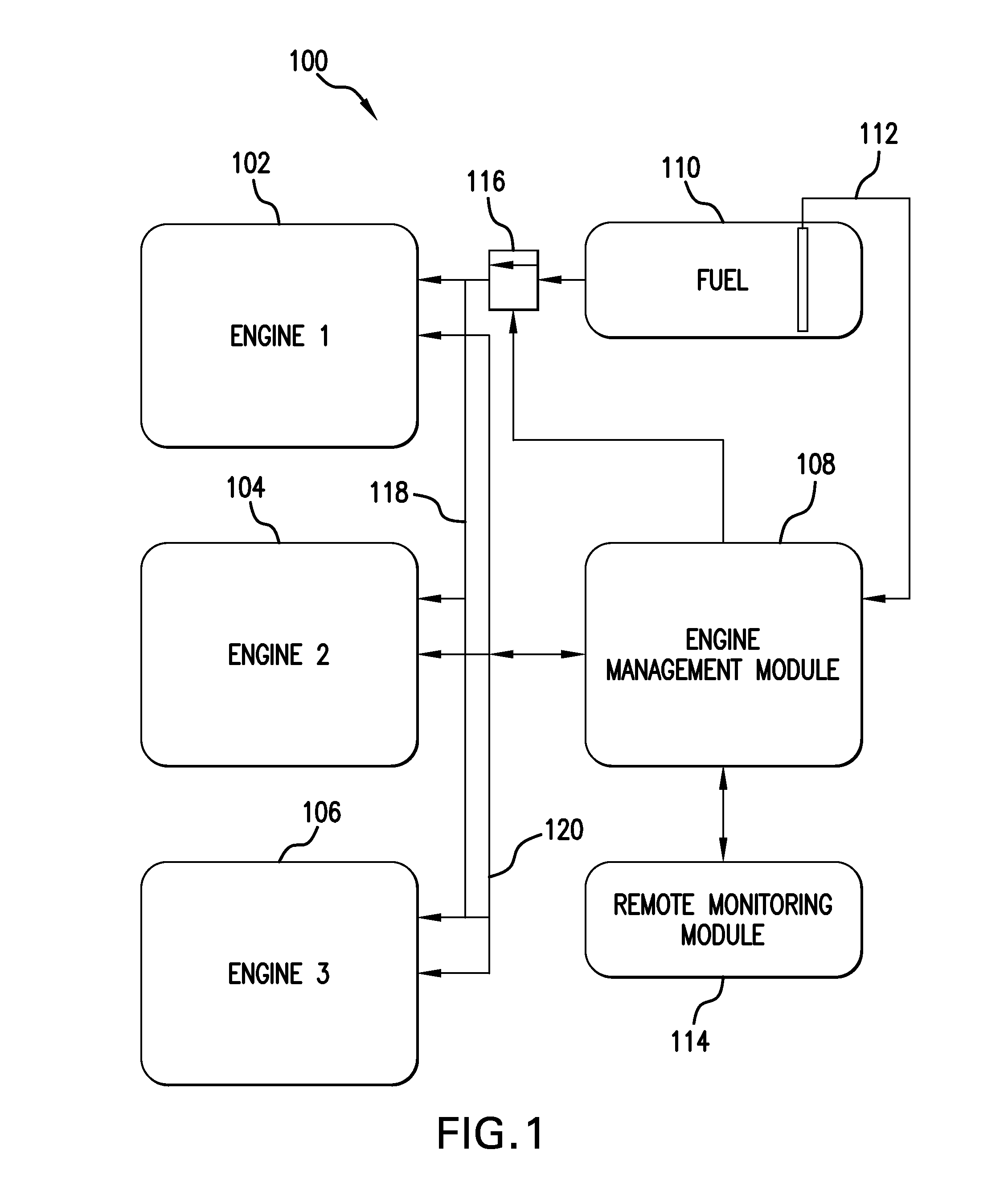
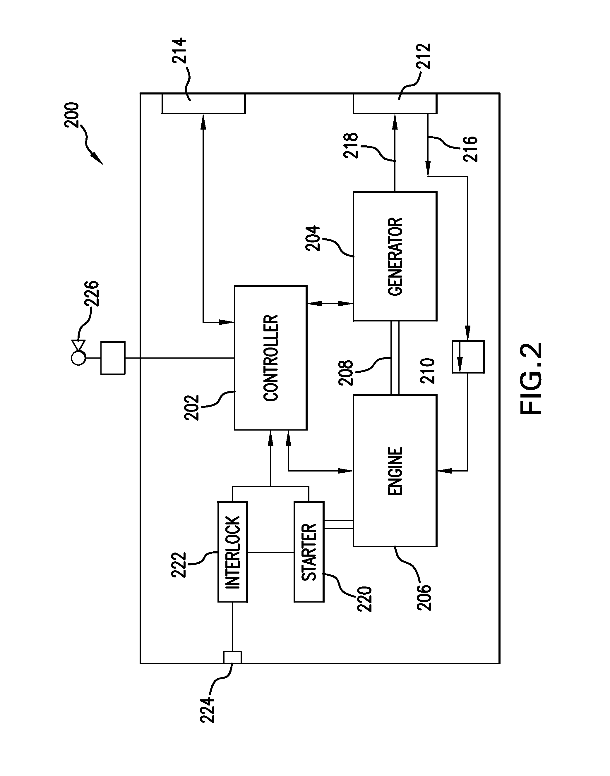
The present invention is a system for managing power and fuel usage on a petroleum drilling rig. The system includes an engine management module that monitors power consumption and recommends methods to manage power use. The engine management module can recommend adding or removing gensets from the power source based on the monitoring data. The system also includes a remote management module that can transmit monitoring and control information to remote terminals. The monitoring can include comparing power consumption to a drilling program to plan future energy needs. The system can also include sensors and fuel measuring mechanisms to monitor fuel usage and detect any unexpected fuel loss. The invention helps manage power and fuel usage to improve the efficiency of drilling rigs.

Problems solved by technology

Given the massive size of today's petroleum extraction rigs, combined with the significant depth to which many rigs are often configured to drill in order to reach viable petroleum deposits, the machines and mechanical equipment on a rig are inherently large and powerful.
The size and power of the machines and mechanical equipment on the rigs necessitates that a substantial amount of electrical power is required to support a drilling operation.
Further, a typical drilling operation includes several phases, where some phases may require significant amounts of electrical power and others may require much less electrical power.
These varying power requirements are further complicated by the fact that drilling rigs are often positioned in remote locations where access to conventional power grids is either not available or presents significant challenges.
However, the conventional bank of generators used to supply power to drilling rigs present several challenges.
Similarly, unnecessarily running generators during non-peak power consumption phases of the drilling operation increases emissions and causes unnecessary wear on the engines and generators.
Further, although some rig crews may attempt to manually shut down unnecessary generators during non-peak power consumption phases of a drilling operation, manually shutting down generators also presents challenges, as the generators must be restarted prior to a peak power consumption period.
The engine powered generators on rigs require some time to warm to optimal operating temperature and are also frequently hard to start in cold temperatures.
If the generators are not restarted in time to meet the need for power, then the drill pipe can be stuck in the hole, or worse case the safety of the crew can be compromised.

Method used


Image

  • Rig fuel management systems and methods
  • Rig fuel management systems and methods
  • Rig fuel management systems and methods

Examples


example 1

Engine Data Test Well Comparison

[0060]The engines in two test wells were compared. Test Well #1 used current engine practice for 43 days, and Test Well #2 used the present systems and methods for 37 days. Test Well #1 utilized $3,660 / day of engine fuel, costing about $158,000 total. In contrast, Test Well #2 utilized $2,600 / day of engine fuel, costing about $97,000 total. Below is a more detailed comparison of the two wells.

Test WellTest WellSavings# 1# 2Typical WellDays4337  40Total Engine Fuel (gal)63,00038,500(−) 21,380   Total Engine Hours (hr)2,6541,716(−) 662 Average Fuel / day (gal)1,4641,040(−) 424 Average Total Engine6246(−) 16Hours / dayAverage Total Eng3738Load / day (%)Number of days running 112 (+) 1EngineNumber of days running 21733(+) 20EnginesNumber of days running 3252(−) 23EnginesAs can be seen from the data above, significant savings were achieved in Test Well #2. The total fuel, engine hours, average fuel / day, and average total engine hours / day were substantially lower...


PUM


Abstract

Systems and methods for managing fuel and electrical power supplied to a drilling rig during all phases of a drilling operation. The system includes a power source in electrical communication with the drilling rig, and an engine management module operatively associated with the power source and configured to monitor power consumption of the drilling rig and recommend methods to manage energy provided thereto.

Description

[0001]This application is a United States national phase application of, and claims priority to, co-pending international application number PCT / US2010 / 036647, filed May 28, 2010, which is incorporated herewith in its entirety.BACKGROUND OF THE INVENTION[0002]1. Technical Field[0003]The present invention is directed to systems and methods of managing fuel use on a drilling rig efficiently during all phases of operation. The system includes a power source, e.g., plurality of engine-generator combinations (gensets), and an engine management module operatively associated with the power source. The engine management module tracks the energy or power required for each rigsite activity and facilitates management of the power source according to the power needs. The fuel management system audits fuel usage on the rig.[0004]2. Background[0005]A drilling rig is generally known as machine or system of machines that are configured to create wells, holes, bores, or shafts in the ground. Drillin...

Claims


Application Information

Patent Timeline
Patent Type & Authority Applications(United States)
IPC IPC(8): E21B44/00
CPCE21B44/00H02J3/38
Inventor BOONE, SCOTT G.
Owner NABORS DRILLING TECH USA INC
Learn More