Surface shape measurement method and measurement apparatus
- Summary
- Abstract
- Description
- Claims
- Application Information
AI Technical Summary
Benefits of technology
Problems solved by technology
Method used
Image

Examples
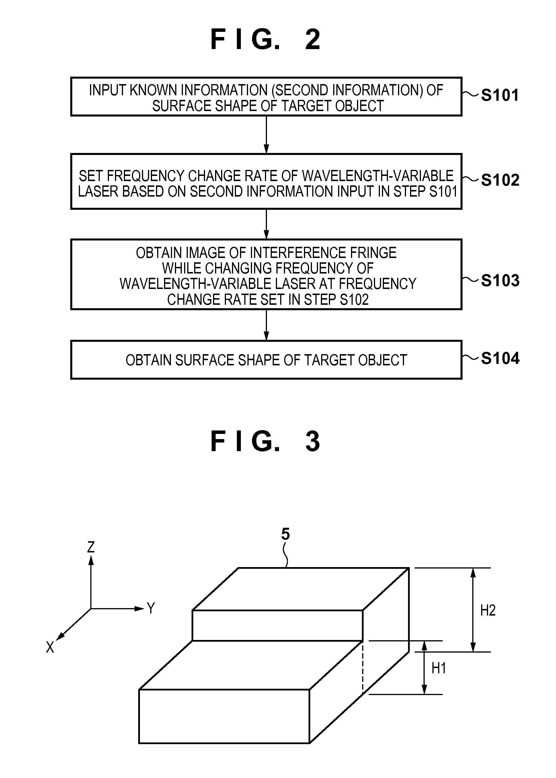
first embodiment
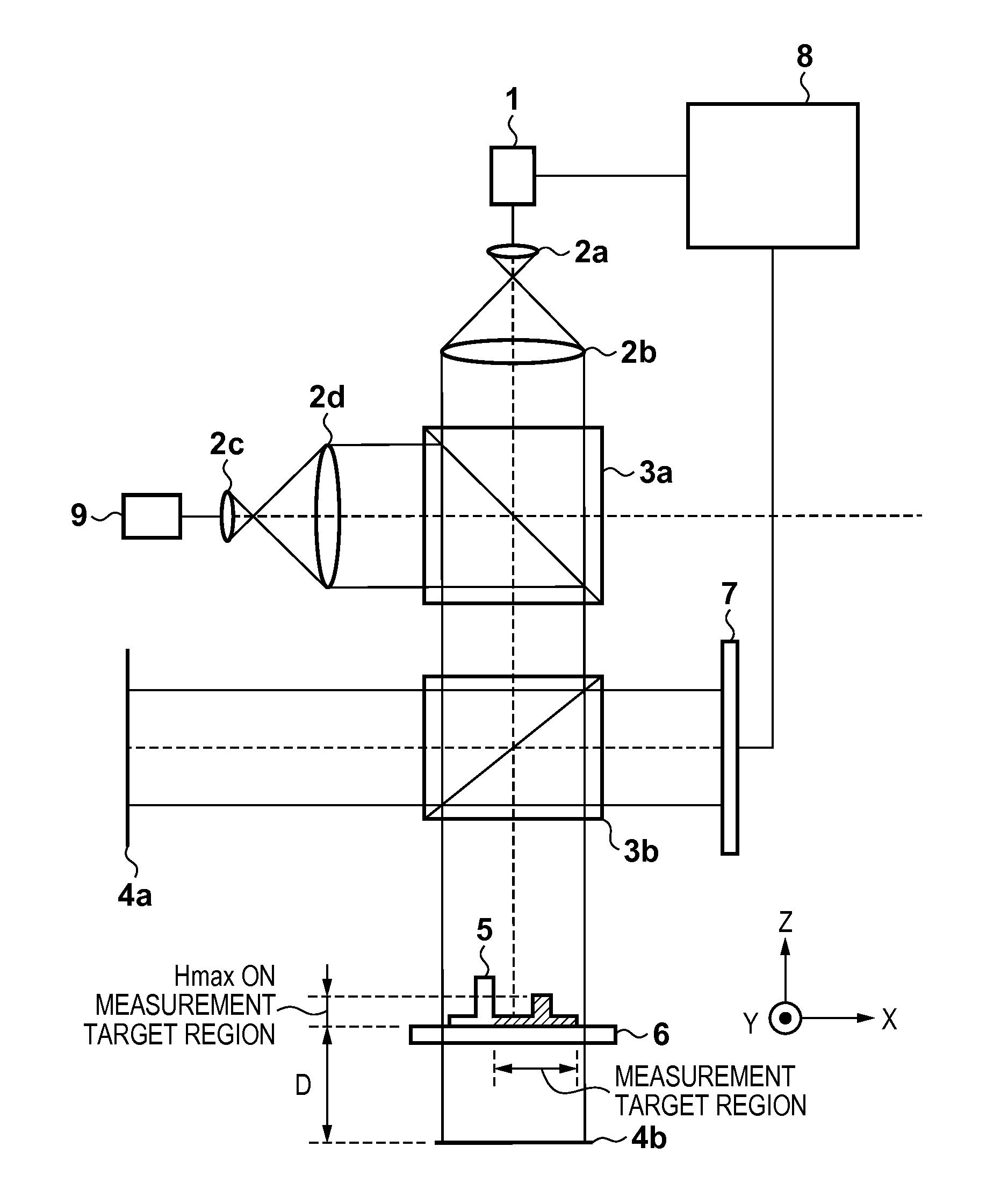
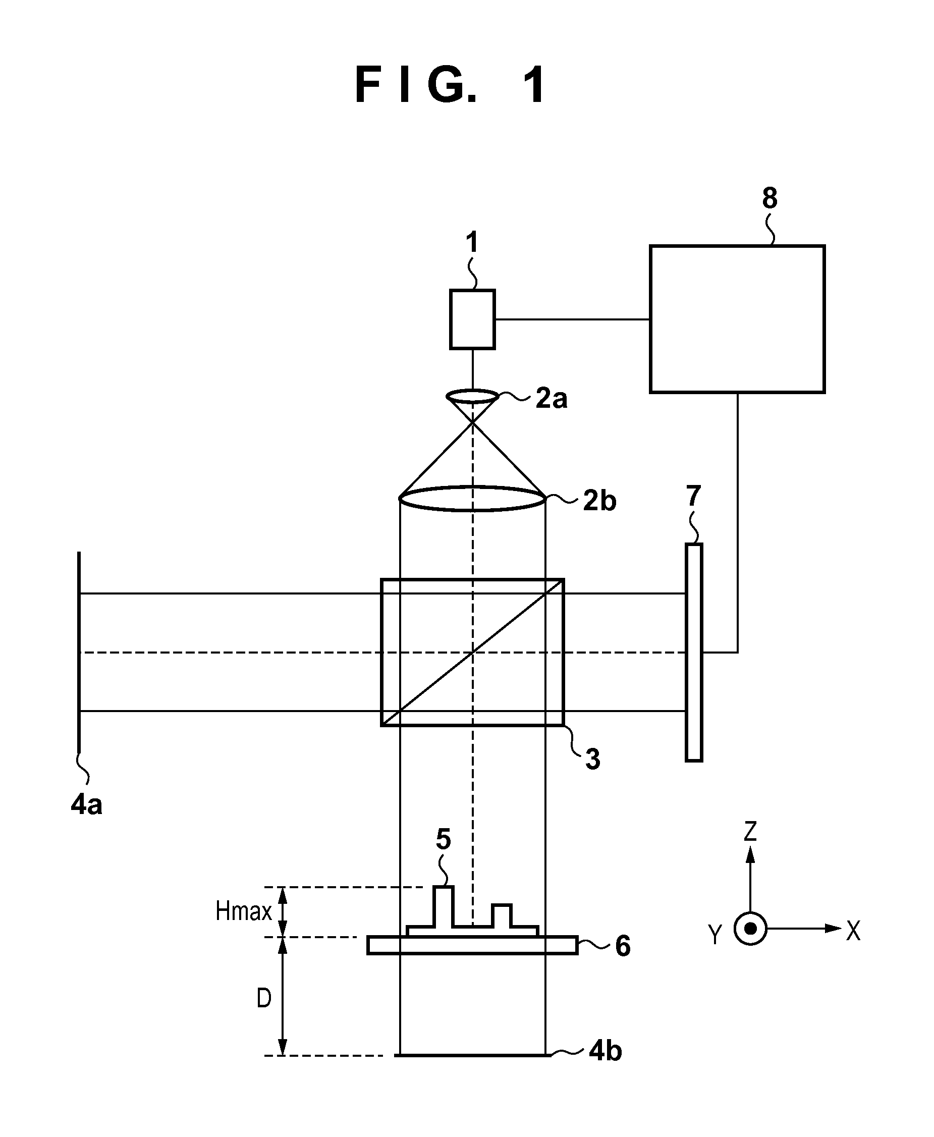
[0021]FIG. 1 shows the arrangement of an apparatus (measurement apparatus) according to the first embodiment, which quickly measures surface shapes of a target object from known information (second information) of the surface shapes of the target object using a wavelength scanning interferometry. The measurement apparatus includes, as a light source, a wavelength-variable laser 1 which emits coherent light while changing its frequency (and wavelength). A processor 8 changes the frequency of the coherent light emitted from the wavelength-variable laser 1 within a certain time range. A light beam emitted from the wavelength-variable laser 1 is magnified by a magnifying lens 2a, is then collimated into parallel light by a collimator lens 2b, and is divided by a beam splitter 3 into light traveling toward a reference surface 4a and that traveling toward a target object 5.
[0022]The light with which the reference surface 4a is irradiated is reflected by the reference surface 4a, and retur...
second embodiment
[0036]A measurement apparatus according to the second embodiment executes a wavelength scanning interferometry by setting a wavelength of a light source to be multi-wavelengths. As a result, if the measurement precision remains the same, the second embodiment can reduce a scan width ΔF of a frequency of the light source compared to the measurement method of the first embodiment. As can be seen from equation (6), the measurement time can be further shortened compared to the first embodiment.
[0037]FIG. 4 is a schematic diagram showing the arrangement of a three-dimensional measurement apparatus of a target object 5 according to the second embodiment. The measurement apparatus uses a wavelength-variable laser 1, which emits coherent light while changing a frequency, as one light source. A processor 8 changes a frequency (wavelength) of a light beam emitted by the wavelength-variable laser 1 within a certain time range. Light having a frequency f1 emitted by the wavelength-variable lase...
third embodiment
[0053]In the third embodiment, a light source which generates incoherent light is added, and a measurement apparatus sets approximate value data of Z dimensions of a target object 5, a position, orientation, and the like of the target object 5 from images based on the incoherent light. The measurement apparatus of the third embodiment changes a frame rate of an image sensor 7 from these set data, measures the Z dimensions of the target object 5 more quickly, and also measures dimensions of a two-dimensional shape projected from the image based on the incoherent light onto an X-Y plane.
[0054]FIG. 6 shows the arrangement of a three-dimensional measurement apparatus of the third embodiment. The measurement apparatus further includes a light source 9, which generates incoherent light, as a light source. A light beam emitted by the light source 9 is magnified by a magnifying lens 2c, and is collimated into parallel light by a collimator lens 2d. The traveling direction of the incoherent ...
PUM
 Abstract
Description
Claims
Application Information
 - Generate Ideas
- Intellectual Property
- Life Sciences
- Materials
- Tech Scout
- Unparalleled Data Quality
- Higher Quality Content
- 60% Fewer Hallucinations
Browse by: Latest US Patents, China's latest patents, Technical Efficacy Thesaurus, Application Domain, Technology Topic, Popular Technical Reports.
© 2025 PatSnap. All rights reserved.Legal|Privacy policy|Modern Slavery Act Transparency Statement|Sitemap|About US| Contact US: help@patsnap.com