Combustion experimental apparatus

Active Publication Date: 2013-09-12
TOHOKU UNIV +1
View PDF2 Cites 3 Cited by
  • Summary
  • Abstract
  • Description
  • Claims
  • Application Information

AI Technical Summary

Benefits of technology

[0016]In the present invention, it is configured so that a temperature-adjusting fluid supply device is capable of causing a temperature-adjusting fluid to flow along a test tube.
[0017]In addition, by changing a flow volume, a temperature, a flow rate or the like of the temperature-adjusting fluid, it is possible to change the state of heating the test tube.
[0018]Consequently, according to the present invention, by changing the flow volume, the temperature, the flow rate or the like of the temperature-adjusting fluid, it is possible to optionally adjust a temperature gradient in the longitudinal direction of the test tube.
[0019]In the present invention, the temperature gradient in the longitudinal direction can be applied to

Problems solved by technology

However, in the ASTM method (ASTM D2155-66, ASTM E659-79), sinc

Method used


Image

  • Combustion experimental apparatus
  • Combustion experimental apparatus
  • Combustion experimental apparatus

Examples


first embodiment

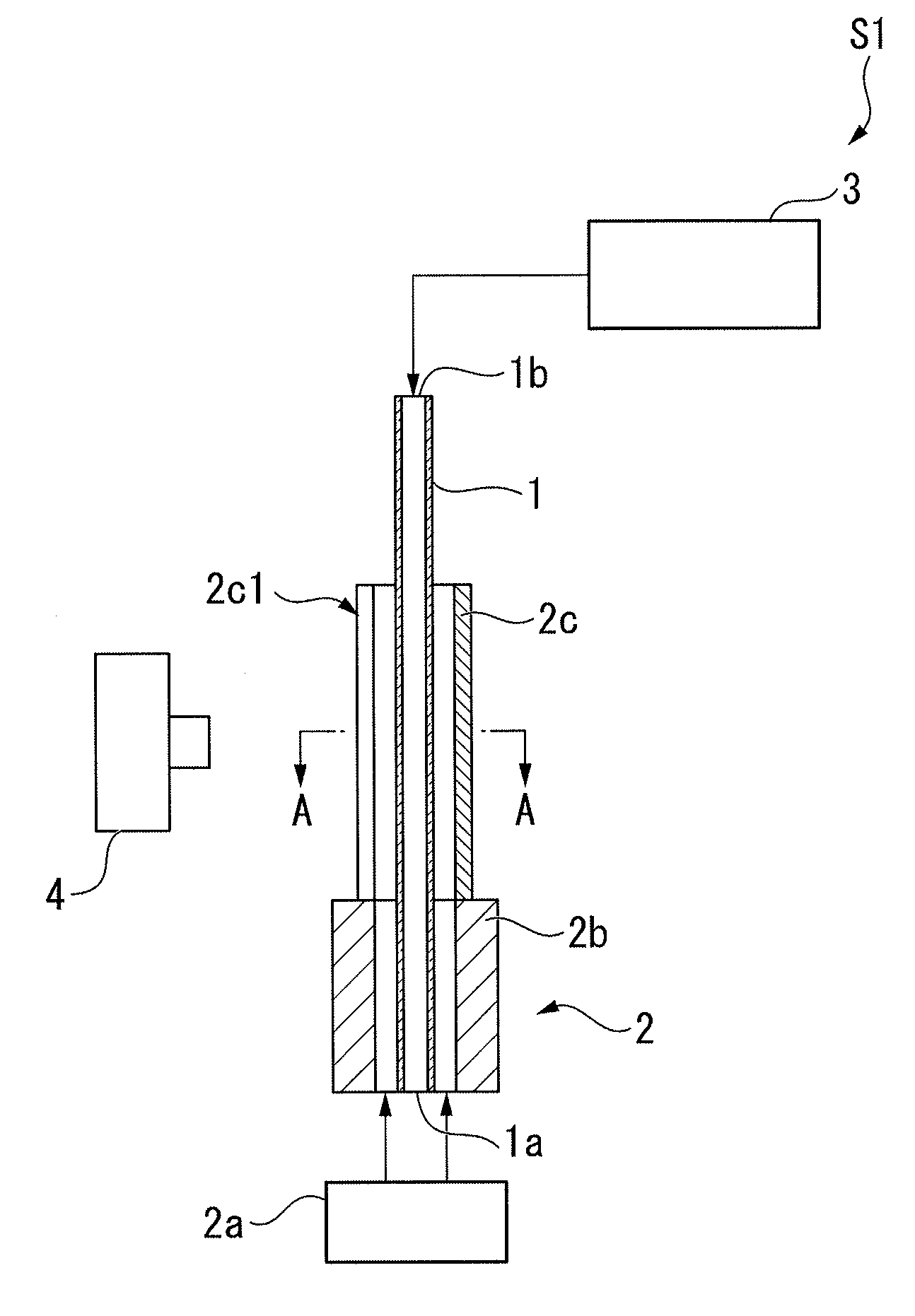
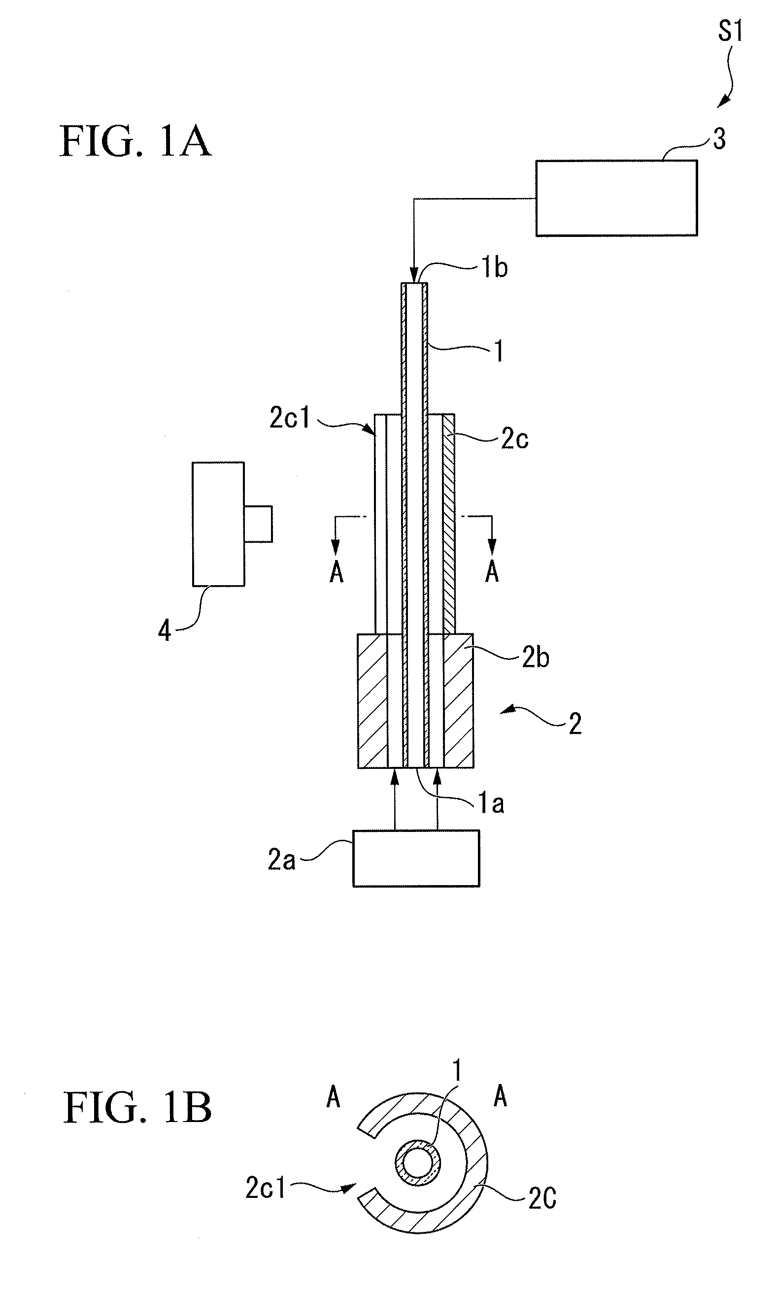
[0030]FIGS. 1A and 1B are schematic views showing the configuration of a combustion experimental apparatus S1 in this embodiment.

[0031]The combustion experimental apparatus S1 in this embodiment is an apparatus to combust test evaluation gas containing fuel, thereby forming flames, and to obtain the positions of the flames, when measuring the ignition temperature of the fuel.

[0032]As shown in FIG. 1A, the combustion experimental apparatus S1 in this embodiment includes a test tube 1, a temperature-adjusting gas supply portion 2 (temperature-adjusting gas supply device), a test evaluation gas supply portion 3 (supply device), and a camera 4 (flame position-obtaining device).

[0033]The test tube 1 is a tube in which flames are formed, and in which the internal flow path thereof has a diameter less than a flame-quenching distance in a normal temperature. In order to transfer flames inside the flow path, the flow path has to have a certain cross-sectional area. If the cross-sectional are...

second embodiment

[0078]Next, a second embodiment of the present invention is described below. In addition, in the description of this embodiment, the explanations regarding the same parts as that of the first embodiment are omitted or simplified.

[0079]FIGS. 3A and 3B are schematic views showing the configuration of a combustion experimental apparatus S2 in this embodiment. As shown in these drawings, the combustion experimental apparatus S2 in this embodiment includes a guide part 2d formed of a glass tube (transparent tube) surrounding the test tube 1 and having the transparency for the light emitted from flames, instead of the guide part 2c included in the combustion experimental apparatus S1 in the first embodiment and formed of a cylindrical heat-insulating member.

[0080]According to the combustion experimental apparatus S2 in this embodiment adopting the above configuration, since the guide part 2d has the transparency for the light emitted from flames, an opening does not have to be provided in...

third embodiment

[0082]Next, a third embodiment of the present invention is described below. In addition, in the description of this embodiment, the explanations regarding the same parts as that of the first embodiment are omitted or simplified.

[0083]FIGS. 4A and 4B are schematic views showing the configuration of a combustion experimental apparatus S3 in this embodiment. As shown in these drawings, the combustion experimental apparatus S3 in this embodiment includes a guide part 2e formed of a heat-insulating member and having openings 2e1 each provided in the side of the camera 4 and in the side opposite to the camera 4, instead of the guide part 2c included in the combustion experimental apparatus S1 in the first embodiment and formed of a cylindrical heat-insulating member.

[0084]According to the combustion experimental apparatus S3 in this embodiment having the above configuration, the positions of flames can be reliably obtained through the opening 2e1 of the guide part 2e provided in the side ...


PUM


Abstract

In a combustion experimental apparatus to obtain the positions of flames formed inside a tube (1), it is possible to adjust a temperature gradient in a longitudinal direction applied to the tube, by including a temperature-adjusting fluid supply device (2) to cause a temperature-adjusting fluid to flow along the tube.

Description

TECHNICAL FIELD[0001]The present invention relates to a combustion experimental apparatus.[0002]Priority is claimed on Japanese Patent Application No. 2010-257844, filed on Nov. 18, 2010, the contents of which are incorporated herein by reference.BACKGROUND ART[0003]Conventionally, when measuring an ignition temperature of flammable liquid used as fuel, the so-called ASTM method (American Standard of Testing Method) is used widely. However, in the ASTM method (ASTM D2155-66, ASTM E659-79), since a combustion space is large, measurement errors become large.[0004]On the other hand, in Patent Document 1, a method is proposed, the method of combusting fuel inside a tube to which a temperature gradient in the longitudinal direction thereof is applied, thereby forming flames therein, and of measuring an ignition temperature of the fuel based on the positions of the flames.DOCUMENT OF RELATED ARTPatent Document[0005][Patent Document 1] Japanese Unexamined Patent Application, First Publicat...

Claims


Application Information

Patent Timeline
IPC IPC(8): G01N25/52
CPCG01N25/52H01L2924/0002H01L2924/00G01N25/50
Inventor MARUTA, KAORUNAKAMURA, HISASHIKATO, SOICHIROOIKAWA, NAOKI
Owner TOHOKU UNIV
Why Eureka
Try Eureka