Fiber optics connection box

a fiber optic connection box and fiber optic technology, applied in the field of fiber optic connection boxes, can solve the problems of increasing inconvenient work, trouble, etc., and achieve the effect of reducing the number of components convenient assembly, and reducing the production cost of the fiber optic connection box

Active Publication Date: 2013-09-12
LS CABLE & SYST LTD
View PDF4 Cites 3 Cited by
  • Summary
  • Abstract
  • Description
  • Claims
  • Application Information

AI Technical Summary

Benefits of technology

[0009]It is another object of the present invention to provide a fiber optics connection box which can be more conveniently assembled by an engineer when the fiber optics connection box is disassembled and reassembled.
[0010]It is yet another object of the present invention to provide a fiber optics connection box in which moisture is prevented from infiltrating into the fiber optics connection box, thereby improving watertightness of the fiber optics connection box, and the number of components constituting the fiber optics connection box is minimized, thereby securing price competitiveness. In accordance with an aspect of the present invention, the above and other objects can be accomplished by the provision of a fiber optics connection box comprising a cover having a receiving space defined therein, a base having an inlet port through which a feeding cable is introduced, the inlet port having a fastening boss, an outlet port through which out cables are withdrawn, the outlet port having a fastening boss, and a pair of through holes through which a passing cable passes via the receiving space of the cover, the base being provided to cover the receiving space, at least one optical processing module provided in the receiving space to split or splice the feeding cable into the out cables, a support frame mounted at the base to support the optical processing module,

Problems solved by technology

In the former case, however, it is necessary for an engineer to handle a heat gun during work of the fiber optics connection box with the result that the engineer may be injured, and, in addition, such work is inconvenient and troublesome.
In this case, the exclusive part for securing such watertightness greatly increases production cost of the fiber optics connection box.

Method used


Image

  • Fiber optics connection box
  • Fiber optics connection box
  • Fiber optics connection box

Examples


Embodiment Construction

[0050]Technology for extending an optical line to a subscriber via an optical network is realized in various ways, such as fiber to the home (FTTH), fiber to the office (FTTO), and fiber to the neighborhood (FTTN).

[0051]Various FTTH technologies have been developed. For example, for a passive optical network (POP), an optical line extends from an optical line terminal of a central office (CO) to a subscriber side, and the optical line is connected to an optical network unit or an optical network terminal of the subscriber side.

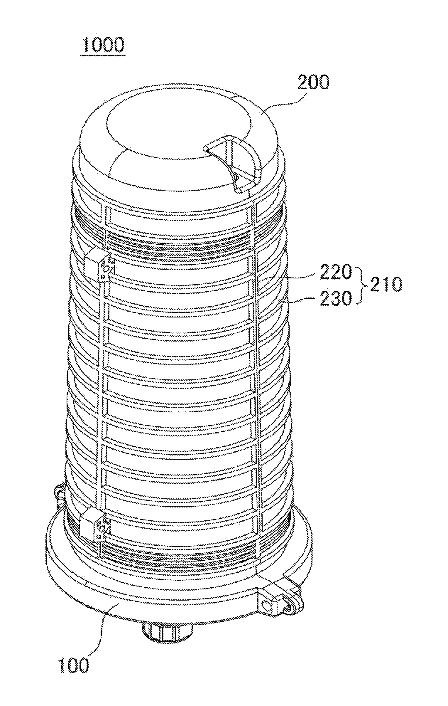
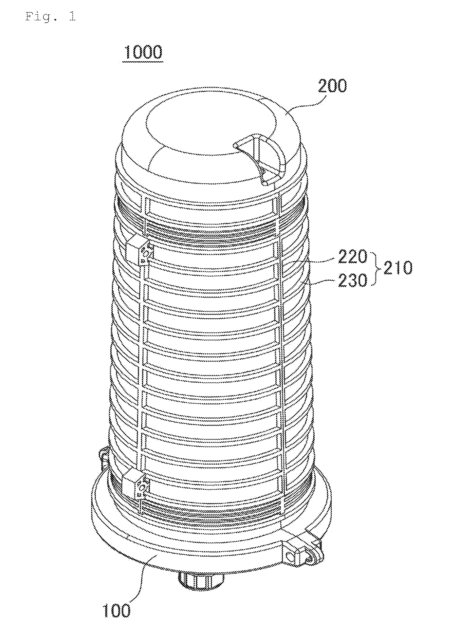
[0052]Upon comparison between the number of optical lines extending from the central office and the number of subscribers, however, the number of the subscribers is much greater than that of the optical lines. For this reason, it is necessary to divide the optical lines extending from the central office so that the number of the optical lines is equal to that of the subscribers. A fiber optics connection box serves to divide the optical lines.

[0053]Specificall...


PUM


Abstract

Disclosed herein is a fiber optics connection box in which a feeding cable introduced into the fiber optics connection box is processed by an optical processing module and is withdrawn as out cables, passing cables pass through a receiving space defined in the fiber optics connection box, thereby improving watertightness, work efficiency, and price competitiveness in a state in which the cables are mounted or while the cables are mounted.

Description

BACKGROUND OF THE INVENTION[0001]1. Field of the Invention[0002]The present invention relates to a fiber optics connection box. More particularly, the present invention relates to a fiber optics connection box with improved watertightness, work efficiency, and price competitiveness.[0003]2. Description of the Related Art[0004]Generally, a fiber optics connection box is installed at a subscriber line, a central office, a relay station, etc. to distribute or connect optical cables so that the optical cables can be connected to a plurality of systems or consumer sides or to treat the remaining portions of the optical cables. Optical cables, supplied from an optical communication supplier, are introduced into consumer sides so that the optical cables can be distributed or connected to the consumer sides. In a case in which such distribution or connection of the optical cables at a specific place is not needed, it may be necessary to treat the remaining portions of the optical cables.[00...

Claims


Application Information

Patent Timeline
Patent Type & Authority Applications(United States)
IPC IPC(8): G02B6/00
CPCG02B6/4454G02B6/4444G02B6/44775
Inventor KIM, SANG YUBCHUNG, HYUP JAEYOON, MYUNG RYUNMOON, TAE SEONCHOI, EUN JUNG
Owner LS CABLE & SYST LTD
Why Eureka
Try Eureka