Method And Apparatus For Space-Division Multiplexing Systems

a multi-mode, space-division technology, applied in multiplex communication, instruments, cladded optical fibres, etc., can solve the problems of affecting the transmission performance of systems, affecting the overall system performance, and affecting the transmission performance of high-order modes. the effect of uniform loss, increased crosstalk, and improved overall system performan

Active Publication Date: 2013-09-12
ALCATEL LUCENT SAS
View PDF36 Cites 48 Cited by
  • Summary
  • Abstract
  • Description
  • Claims
  • Application Information

AI Technical Summary

Benefits of technology

[0008]According to one embodiment of a MCF-based transmission system, the optical signals traveling through each of the cores of a MCF span are moved to another core in the next MCF span. This core-to-core signal rotation may be continued at multiple locations along a MCF transmission link. The locations where the core-to-core rotation is applied can be (1) optical add / drop multiplexer (OADM) sites, (2) optical amplifier sites, or (3) the combination of (1) and (2). By doing the core-to-core rotation, the uniformity in loss, dispersion, and signal arrival time can be much improved, thereby increasing the overall system performance. As it is likely that one or more cores or modes will have increased crosstalk relative to the others, embodiments of the described technique can help reduce the performance variation of spatially multiplexed signals by distributing the crosstalk penalty among all of the spatially multiplexed signals. In addition, the system degradation resulting from some optical component defects, such as the loss ripple and polarization-dependent loss (PDL) in OADMs and optical amplifiers, can be reduced through the “averaging” effect of the core-to-core rotation.

Problems solved by technology

Performance variations among signals traveling through transmission media impair the transmission performance of systems, including for example the transmission performance of space-division multiplexing (SDM) systems.
Thus, one technical problem related to such transmission systems is how to increase the transmission performance of SDM systems using multi-core fiber (MCF), multi-mode fiber (MMF), few-mode fiber (FMF), or ribbon cable made of nominally uncoupled single-mode fiber (SMF) as the transmission media.
However, this approach has limited performance benefits and becomes increasingly expensive as the uniformity requirement is increased.
Further, for MMF, higher-order modes generally have higher loss than the fundamental mode, and it is difficult to make the losses of different modes equal.

Method used


Image

  • Method And Apparatus For Space-Division Multiplexing Systems
  • Method And Apparatus For Space-Division Multiplexing Systems

Examples


Embodiment Construction

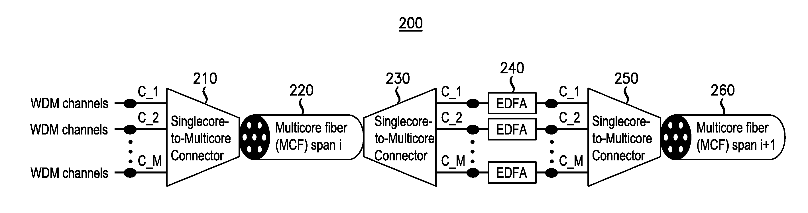
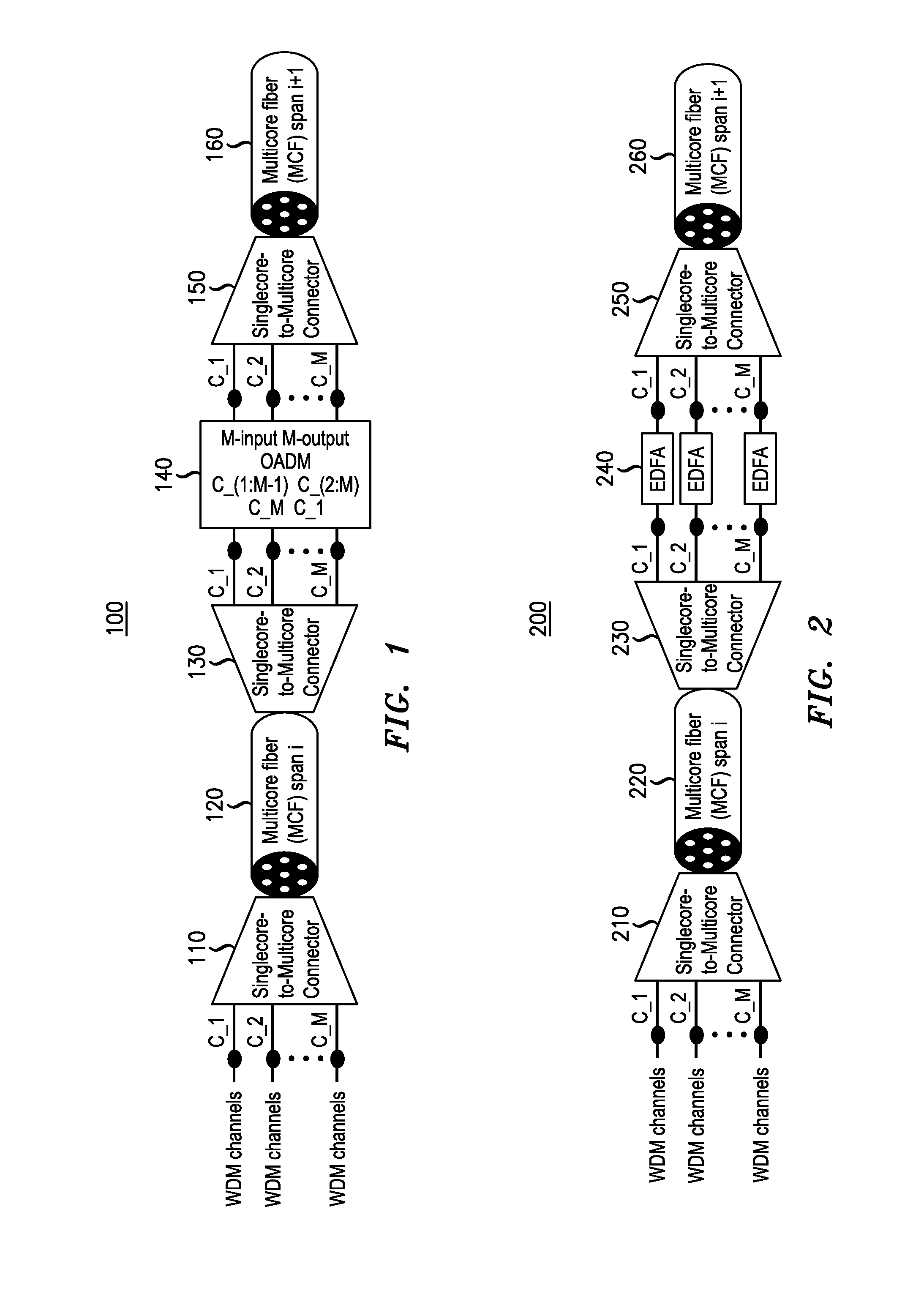
[0013]FIG. 1 shows a block diagram of a first embodiment of a space division multiplexed (SDM) transmission system according to an embodiment of the invention.

[0014]FIG. 1 illustrates a first embodiment for core-to-core signal rotation in multi-core fiber (MCF) transmission for a SDM transmission system 100. The optical signals traveling through a MCF span are rearranged such that they travel through the next MCF span on different cores of the MCF. As shown, wavelength-division multiplexed (WDM) channels (C—1, C—2, . . . C_M) may be provided to a singlecore-to-multicore-connector 110 for connection to a first MCF span 120. (A fiber span may also be called a fiber segment.) The channels are provided to the first MFC span with a first spatial assignment. Naturally, the optical signal or channels need not utilize wavelength-division multiplexing.

[0015]The MCF span 120 is traversed by the optical signals and provided to a singlecore-to-multicore-connector 130. At this point, the spatial...


PUM


Abstract

A space division multiplexed (SDM) transmission system that includes at least two segments of transmission media in which a spatial assignment of the two segments is different is provided. For example, the SDM transmission may include a first segment of transmission media having a first spatial assignment and a second segment of transmission media having a second spatial assignment, wherein the first spatial assignment differs from the second spatial assignment. An example method obtains an optical signal on a first segment of transmission media having a first spatial assignment and forwards the optical signal on a second segment of transmission media with a different spatial assignment. The transmission media may be a multi-core fiber (MCF), a multi-mode fiber (MMF), a few-mode fiber (FMF), or a ribbon cable comprising nominally uncoupled single-mode fiber (SMF).

Description

CROSS-REFERENCE TO RELATED APPLICATIONS[0001]This application claims priority from U.S. Provisional Patent Application No. 61 / 530,929, filed on Sep. 2, 2011, entitled “Method and Apparatus for Space-Division Multiplexing Systems,” which is incorporated herein by reference in its entirety.BACKGROUND[0002]1. Field[0003]The invention relates to optical communication equipment and, more specifically but not exclusively, to transmission of optical communication signals in space-division multiplexing (SDM) systems using multi-core fiber (MCF), multi-mode fiber (MMF), few-mode fiber (FMF), or ribbon cable made of nominally uncoupled single-mode fiber (SMF) as the transmission media.[0004]2. Description of the Related Art[0005]This section introduces aspects that may help facilitate a better understanding of the invention(s) described herein. Accordingly, the statements of this section are to be read in this light and are not to be understood as admissions about what is in the prior art or ...

Claims


Application Information

Patent Timeline
Patent Type & Authority Applications(United States)
IPC IPC(8): H04Q11/00
CPCH04J14/04G02B6/02042G02B6/26H04J14/0212H04J14/00H04J14/02H04J14/021H04Q11/0003G02B6/29383
Inventor SETHUMADHAVAN, CHANDRASEKHARLIU, XIANGWINZER, PETER J.GNAUCK, ALAN H.
Owner ALCATEL LUCENT SAS
Why Eureka
Try Eureka