Power converter

Active Publication Date: 2015-12-31
HITACHI ASTEMO LTD
View PDF24 Cites 14 Cited by
  • Summary
  • Abstract
  • Description
  • Claims
  • Application Information

AI Technical Summary

Benefits of technology

[0008]According to the invention, it is possible to achieve improvement of the cooling

Problems solved by technology

Even if strict fitting tolerance is set and the gap is made small, due to a manufacturing variation of the power semiconductor module itself, there is a concern that interference by members may occur not in a sealing section.
Particularly, if a plurality of power semiconductor modules are provided (a plurality of sealing sections are provided), it is not realistic to strictly regulate the fitting tolerance.
Thus, if the power semiconductor module and t

Method used


Image

  • Power converter
  • Power converter
  • Power converter

Examples


first example

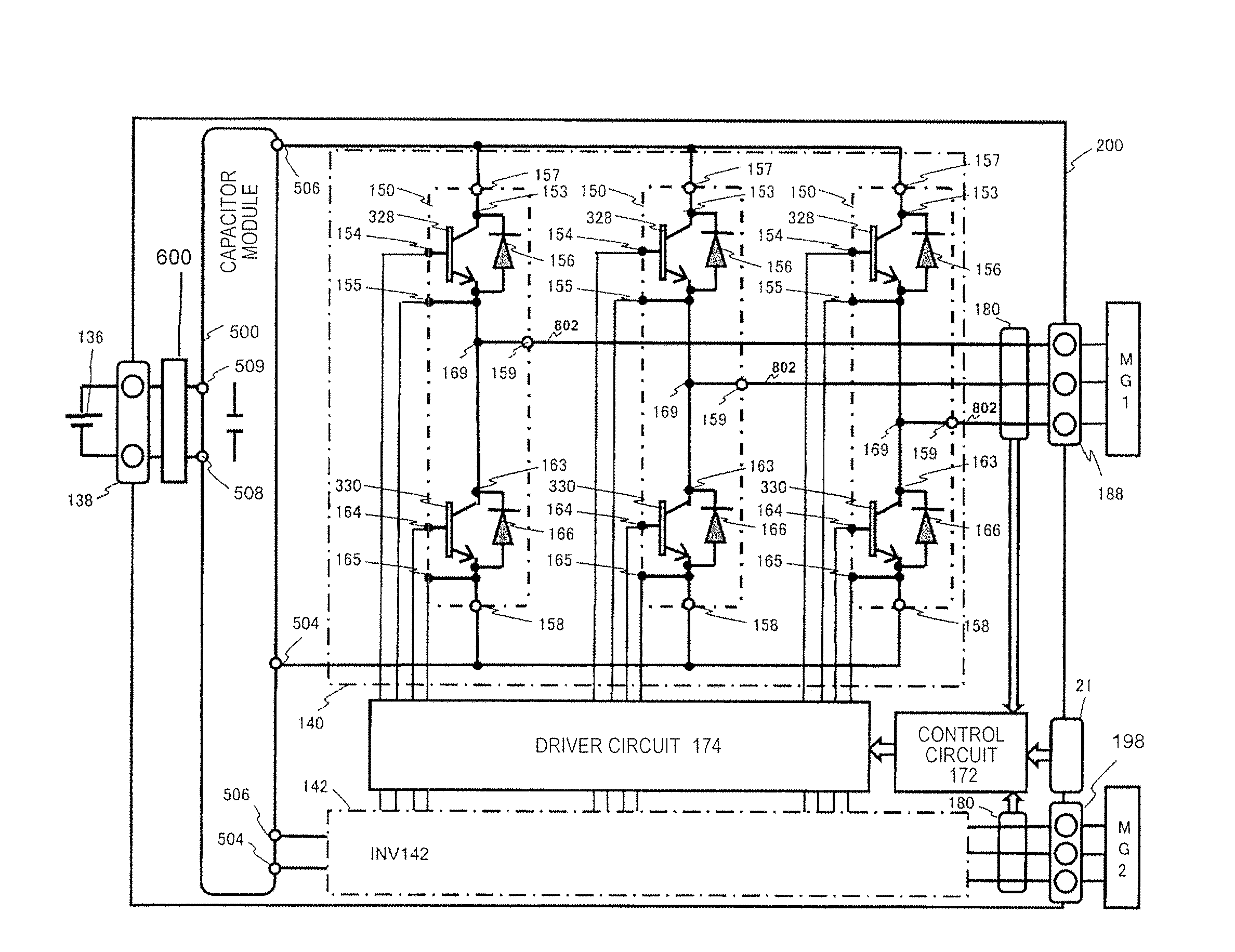
[0029]FIG. 3 is a diagram illustrating a control block of a hybrid electric vehicle (hereinafter, described as “HEV”). An engine EGN, a motor generator MG1, and a motor generator MG2 generate a driving torque of the vehicle. Furthermore, the motor generator MG1 and the motor generator MG2 not only generate a rotary torque but also have a function for converting a mechanical energy applied from the outside to the motor generator MG1 or the motor generator MG2 into electric power.

[0030]For example, the motor generators MG1 and MG2 are synchronous motors or induction motors and, as described above, operate as motors or generators depending on an operating method. If the motor generators MG1 and MG2 are mounted on the vehicle, it is desired to obtain a high output despite a small size and a permanent magnet-type synchronous motor using a magnet such as neodymium is suitable for the motor generators MG1 and MG2. Furthermore, the permanent magnet-type synchronous motor generates less heat...

second example

[0102]A schematic configuration of a power converter 200 of a second example will be described with reference to FIGS. 10 and 11. FIG. 10 illustrates a modification example in which the flow path forming member 2 of the first example is changed to a first flow path forming member 2a and a second flow path forming member 2b. Since the other configurations are the same as the configurations of the first example, detailed description will be omitted.

[0103]The first flow path forming member 2a is mounted on a power semiconductor module 150a from the same direction as a refrigerant traveling direction similar to when the flow path forming member 2 is mounted on the power semiconductor module 150a in the first example. Here, in the first example, the flow path forming member 2 is mounted so as to hold all of three power semiconductor modules 150a, but in this embodiment, two adjacent power semiconductor modules 150a among three power semiconductor modules 150a are mounted on the first flo...

third example

[0111]A schematic configuration of a power converter 200 of a third example will be described with reference to FIG. 12.

[0112]FIG. 12 illustrates a modification example in which three power semiconductor modules 150a are respectively housed in different module housing spaces 20a.

[0113]In this embodiment, three module housing spaces 20a are formed in a casing 20. The three module housing spaces 20a are connected in series and form a refrigerant flow path from an inlet pipe 30a to an outlet pipe 30b. The first example and the second example are different from this example in that the three power semiconductor modules 150a are housed in one module housing space 20a.

[0114]Similar to the first example and the second example, the power semiconductor module 150a is housed in the module housing space 20a in a state where a flow path forming member 2c is mounted. In this embodiment, the flow path forming member 2c is mounted on each of the three power semiconductor modules 150a.

[0115]In t...


PUM


Abstract

A power converter includes a power semiconductor module, a first flow path forming body and a second flow path forming body that forms a housing space for storing the power semiconductor module and the first flow path forming body, in which the first flow path forming body is configured of a first side wall section, a second side wall section, and a bottom surface section, the first side wall section forms a first flow path space between one surface of the power semiconductor module and the first side wall section, the second side wall section forms a second flow path space between the other surface of the power semiconductor module and the second side wall section, and cooling refrigerant flows through the housing space, the first flow path space, and the second flow path space.

Description

TECHNICAL FIELD[0001]The present invention relates to a power converter and, particularly, to a power converter that is used in a hybrid electric vehicle or an electric vehicle.BACKGROUND ART[0002]In an electric vehicle or a hybrid electric vehicle, miniaturization or cost reduction of components to be mounted is important, a power converter converting a DC current of a battery into an AC current is not an exception and miniaturization or cost reduction thereof is being demanded. Accordingly, it is necessary to improve cooling performance because power density is increased as a result of this.[0003]A power semiconductor module has the largest heat generation amount among electronic components configuring the power converter. In order to improve cooling performance of the power semiconductor module, a double-sided cooling structure (PTL 1) has been effective in which thermal grease having a large thermal resistance is removed and heat is radiated from both surfaces of a semiconductor...

Claims


Application Information

Patent Timeline
IPC IPC(8): H05K7/20H02M7/539
CPCH02M7/003H05K7/20927H02M7/5387H02M7/539H05K7/2089
Inventor HORIUCHI, KEISUKEHARA, YOSEIKUWANO, MORIONISHIHARA, ATSUONAKATSU, KINYA
Owner HITACHI ASTEMO LTD
Why Eureka
Try Eureka