Power supply device and image forming apparatus

a technology of power supply device and image forming apparatus, which is applied in the direction of electric variable regulation, process and machine control, instruments, etc., can solve the problems of low switching frequency, loss of switching power supply in light load operation, and large transformer size, so as to reduce vibration noise, increase loss, and reduce the effect of vibration nois

Inactive Publication Date: 2013-09-12
CANON KK
View PDF4 Cites 24 Cited by
  • Summary
  • Abstract
  • Description
  • Claims
  • Application Information

AI Technical Summary

Benefits of technology

[0010]In view of the above-mentioned circumstances, the purpose of the present invention is to provide a switching power supply capable of reducing vibration noise generated from a transformer in a light load operation without increasing the size of the transformer and without increasing a loss caused by switching.

Problems solved by technology

Most of the losses of the switching power supply in the light load operation are caused by the switching operation.
The long inactive period, however, leads to a low switching frequency.
However, the use of a core material having a large cross-sectional area for the transformer increases the size of the transformer, which makes it difficult to downsize the device.
The method of shortening the turn-on time of the switching element can reduce the turn-on time and reduce the change in magnetic field to alleviate the vibration noise of the transformer, but increases the number of switchings per unit time, resulting in a larger switching loss.
The method of changing the driving current waveform of the transformer to be gradually larger or gradually smaller is difficult to be applied to the reduction in power consumption if energy to be supplied to a load on the secondary side is small.
This is because it is difficult for the soft-start circuit to change the current waveform to be gradually larger or gradually smaller in the light load operation.
The former method increases the switching loss to deteriorate efficiency, and the latter method increases the cost.
In other words, in order to reduce the number of switchings to alleviate the switching loss in the switching power supply, energy per pulse applied to the transformer is increased, and hence large sound is generated, which is a tradeoff.

Method used


Image

  • Power supply device and image forming apparatus
  • Power supply device and image forming apparatus
  • Power supply device and image forming apparatus

Examples


first embodiment

[0035](Configuration of Power Supply Circuit)

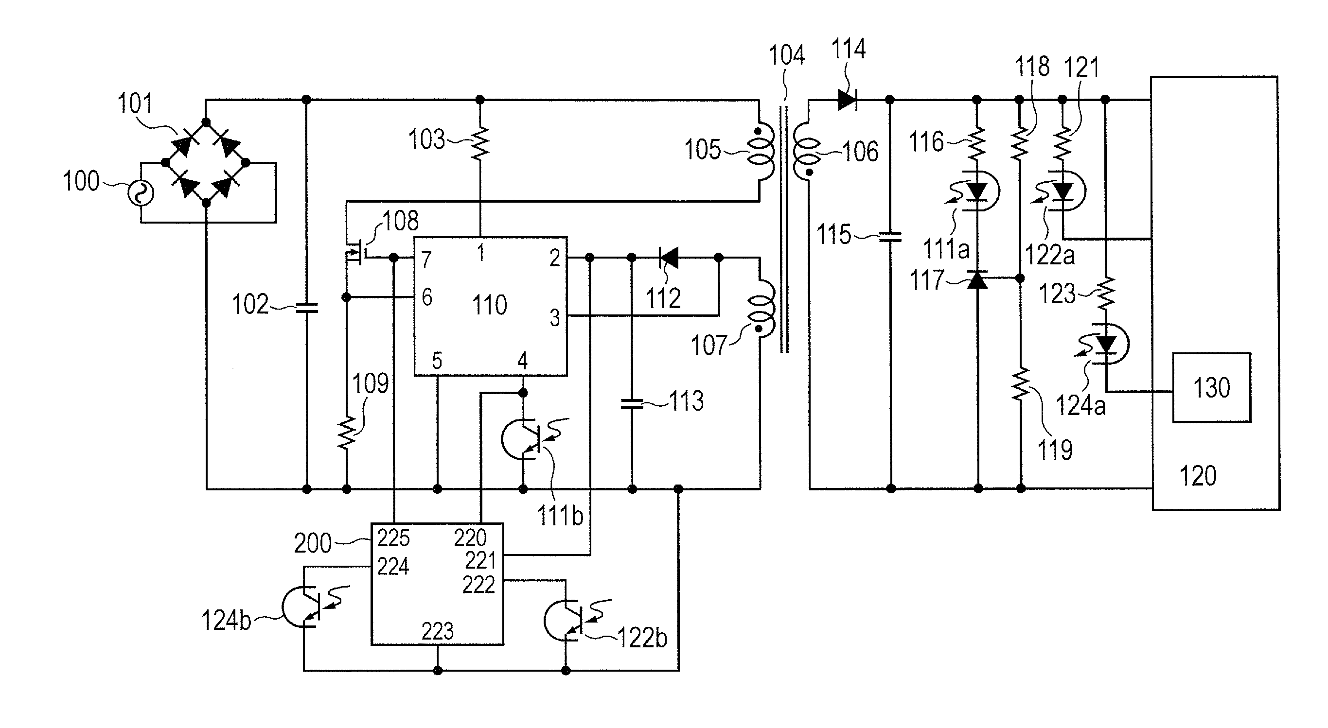
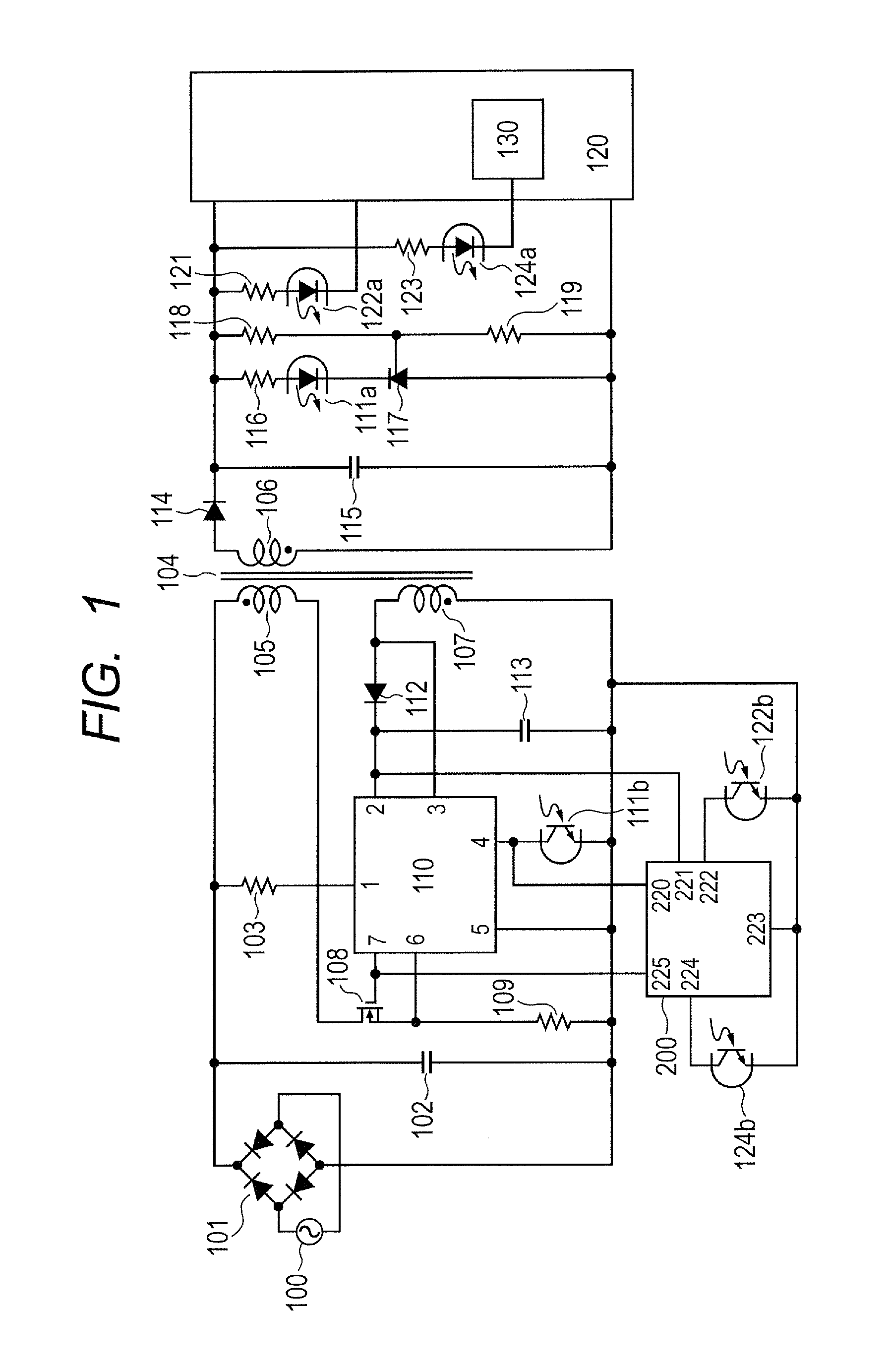
[0036]FIG. 1 illustrates a circuit diagram of a switching-mode power supply (hereinafter also referred to as switching power supply) according to a first embodiment of the present invention. The circuit diagram exemplified in this embodiment is a quasi-resonant switching power supply. This embodiment describes a commonly-used quasi-resonant IC as an example of a switching control IC 110.

[0037]Description is given of the switching control IC 110. A terminal 1 of the switching control IC 110 is a start-up terminal. A terminal 2 of the switching control IC 110 is a power supply terminal. When a voltage from the terminal 2 of the switching control IC 110 is low, a high voltage switch is turned ON so that power is supplied to the switching control IC 110 via a start-up resistor 103 provided outside the switching control IC 110, and the switching control IC 110 operates. When a switching element 108 of FIG. 1 is turned ON and OFF, a voltage is ...

second embodiment

[0079]A second embodiment of the present invention is different from the first embodiment in that a switching control IC 900 equipped with an internal forced turn-off time control circuit having the same effect as the forced turn-off time control circuit 200 is used.

[0080](Circuit Diagram of Power Supply Device)

[0081]FIG. 8A illustrates a circuit diagram in this embodiment. The same configurations as those described with reference to FIG. 1 are denoted by the same reference symbols, and description thereof is omitted. The circuit operation other than the switching control IC 900 and a resistor 125 is the same as the circuit operation described in the first embodiment, and hence description of the operation is also omitted.

[0082]First, an internal function of the switching control IC 900 is described. FIG. 8B illustrates an internal block diagram of the switching control IC 900. The operations of the terminal 1 and the terminal 2 of the switching control IC 900 are the same as those ...

third embodiment

[0105]A third embodiment of the present invention is different from the first and second embodiments in that the short-cycle pulse stop time and the long-cycle pulse stop time are simultaneously varied in the drive pulses for driving the switching power supply. In this case, the long-cycle interval in the burst operation can be regarded also as an interval in which the switching operation of the switching control IC 900 is inactive.

[0106](Circuit Diagram of Power Supply Device)

[0107]FIG. 10A illustrates a circuit diagram in this embodiment. The same configurations as those described with reference to FIG. 1 of the first embodiment and FIG. 8A of the second embodiment are denoted by the same reference symbols, and description thereof is omitted. The circuit operation other than a transistor 126 and resistors 127 and 128 is the same as the circuit operation described in the second embodiment, and hence description of the operation is also omitted.

[0108]FIGS. 10B to 10D are voltage wav...


PUM


Abstract

The power supply device includes a transformer, a switching unit for driving a primary side of the transformer, a control unit for outputting a pulse signal to the switching unit to control a switching operation including a period during which the switching unit is active and a period during which the switching unit is inactive, in order to output predetermined electric power from a secondary side of the transformer, and an output control unit for continuously outputting a pulse signal to the control unit in the period during which the switching unit is active, at a predetermined cycle shorter than the period during which the switching unit is inactive.

Description

BACKGROUND OF THE INVENTION[0001]1. Field of the Invention[0002]The present invention relates to a power supply device and an image forming apparatus, and more particularly, to a DC / DC converter.[0003]2. Description of the Related Art[0004]In recent years, in view of demands for a power-saving device in various electronic devices, further power saving is required also for a power supply of the electronic devices. As an example of the power supply of the electronic devices, there is used a switching-mode power supply (hereinafter referred to as switching power supply) for outputting a target voltage by driving and turning ON and OFF a switching element such as a field effect transistor (FET) at a predetermined frequency. In some types of the switching power supply, the number of switching operations of the switching element is reduced in a power-saving operation (referred to also as light load operation) to improve efficiency. The specifications for power saving have been subject to ...

Claims


Application Information

Patent Timeline
Patent Type & Authority Applications(United States)
IPC IPC(8): G03G15/00H02J1/00
CPCH02M3/33507H02M3/28G03G15/80H02M3/33523G03G15/00H02M1/12H02M1/42
Inventor NAKAJIMA, YUKIHAYASAKI, MINORU
Owner CANON KK
Why Eureka
Try Eureka