Rock bolt sealing system

a technology of sealing system and rock bolt, which is applied in the direction of anchoring bolts, mining structures, earthwork drilling and mining, etc., can solve the problems of accumulated water, need for pumping and line maintenance, and use of the above-described split s

Inactive Publication Date: 2013-09-12
SMITH ERIC W +1
View PDF9 Cites 25 Cited by
  • Summary
  • Abstract
  • Description
  • Claims
  • Application Information

AI Technical Summary

Benefits of technology

[0011]The present invention also includes a method for sealing a rock bolt from water leakage comprising: inserting a sealable rock bolt assembly comprising a bearing plate, an elongated member having a top, bottom, and containing annular space when placed in a pre-formed hole in the rock to receive expanded resin; and a sealing unit located proximate to the annular space. The method may also be performed by installing the sealable rock bolt assembly and then installing the sealing unit and any other optional components. The elongated member may have a hollow interior. The to sealing unit comprises a container having sides and two ends and comprised of a water degradable material and having both ends capped with a water degradable material. The container contains a liquid water activated, expandable hydrophobic pre-polymeric resin suitable to be expanded into the pre-formed hole in the rock, which rock contains water. Once the rock bolt is fitted into and secured in a pre-formed hole located in the roof, side or bottom of the rock, water present in the rock, such as in a fissure, contacts the sealing unit to cause the water dissolvable materials to dissolve. Thereby the liquid water activated, expandable hydrophobic pre-polymeric resin is contacted with the water to form an expanded polymeric resin which fills and seals the annular space proximate to the rock bolt, i.e., between the inner diameter of the pre-formed hole and the outer diameter of the rock bolt to the top of the hole, to prevent water flow from the rock through or beside the rock bolt.
[0012]The present invention also includes another method embodiment for sealing a rock bolt from water comprising forming an opening that has an open end and a closed end and placing a resin-containing unit at the closed end. A sealable rock bolt assembly is then inserted into the opening. The rock bolt assembly comprises a bearing plate and an elongated member having a top and bottom. Annular space proximate to the rock bolt is created upon insertion of the bolt into the opening. Such insertion causes contact with and puncture of the resin-containing unit by the rock bolt thereby causing the resin to cure and to secure said rock bolt assembly at the closed end of the pre-formed opening. Then a sealing unit is inserted into the opening proximate to its closed end. The sealing unit comprises a container having sides and two ends and comprised of a water degradable material and having both ends capped with a water degradable material. The sealing unit contains a liquid water activated, to expandable hydrophobic pre-polymeric resin. Upon contact of the sealing unit with water, the water dissolvable materials to dissolve; and the liquid water activated, expandable hydrophobic pre-polymeric resin forms an expanded polymeric resin which causes filling and sealing of the annular space proximate to the rock bolt to prevent water flow from the rock through or around the rock bolt. This method embodiment may further include inserting a water-containing unit between the closed end and sealing unit and causing said water-containing unit to release water to activate the resin contained in the sealing unit. Such embodiment may be useful in instances where the opening is dry or does not contain sufficient water to dissolve the outer portions of the sealing unit or to sufficiently expand the resin contained in the sealing unit to achieve the desired seal.

Problems solved by technology

A problem has existed regarding the use of the above-described Split Set, point anchor, point anchor resin, and Swellex rock bolts.
Such drainage results in undesirable wet conditions and can result in corrosion of the rock bolt, the need for pumping accumulated water, increased maintenance of pumps and lines, the need to treat water prior to discharge as well the creation of safety issues.
This long standing problem in the art has not been satisfactorily addressed to date.
The above patent publication and patents do not contain a water-dissolvable sealing unit which contains a water-activated expandable hydrophobic pre-polymeric resin and thus do not function in the above described manner to create a seal against water leakage.

Method used


Image

  • Rock bolt sealing system
  • Rock bolt sealing system
  • Rock bolt sealing system

Examples


example 1

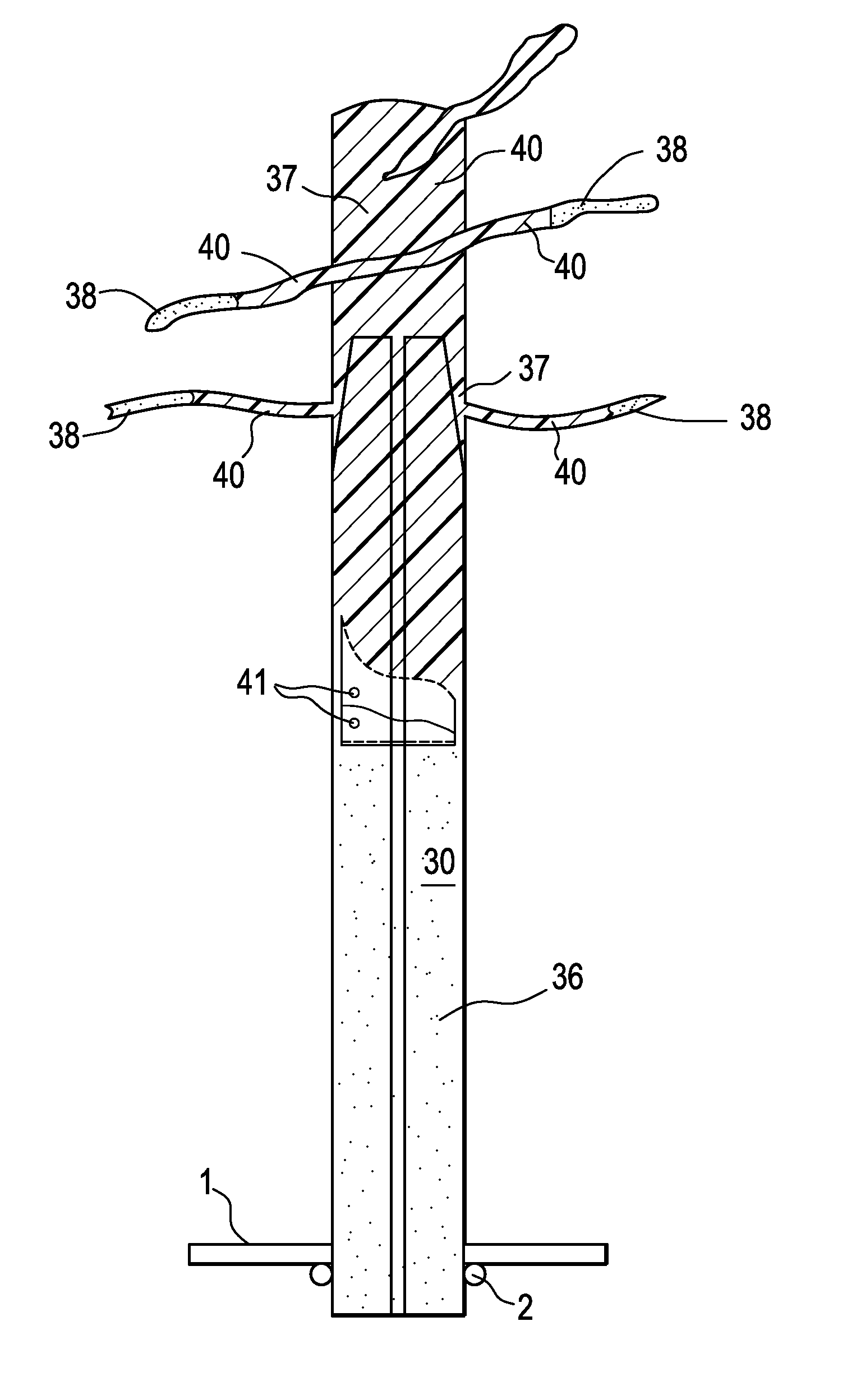
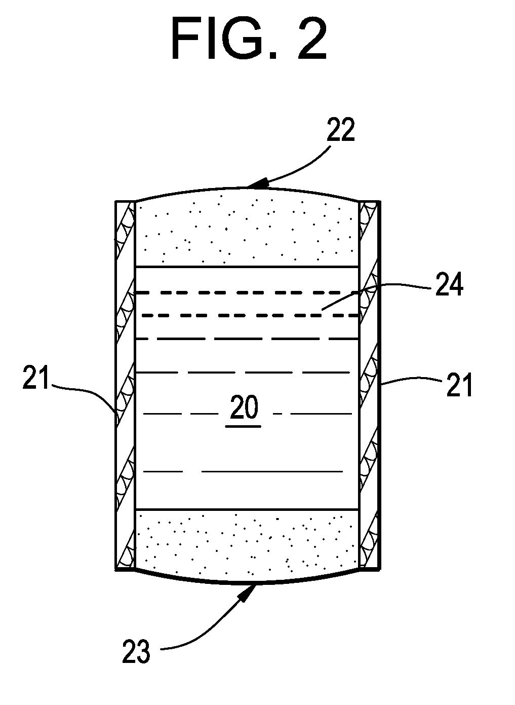
[0033]This Example pertains to the preparation of a sealed rock bolt assembly suitable for use in the method of the invention and comprises the following steps.[0034]1. A sealing unit is prepared by placing a salt cap on one end of a soap tube and then dispensing a liquid water-activated, expandable hydrophobic pre-polymeric resin into the tube and then placing a second salt cap on the opposite end of the soap tube;[0035]2. Inserting the prepared sealing unit inside a hollow Split Set rock bolt toward the tapered end of the rock bolt;[0036]3. Dispensing a heavy bead of a fast reacting polyurethane polymer into the interior of the rock bolt to form a cured foamed reaction product located between the sealing unit and the bottom portion of the rock bolt; and[0037]4. Trimming any excess of foamed material from the rock bolt.

[0038]As noted above, this Examples 1, 2, and 3 may be performed by inserting the sealing unit inside the Split Set rock bolt before or after insertion of the rock b...

example 2

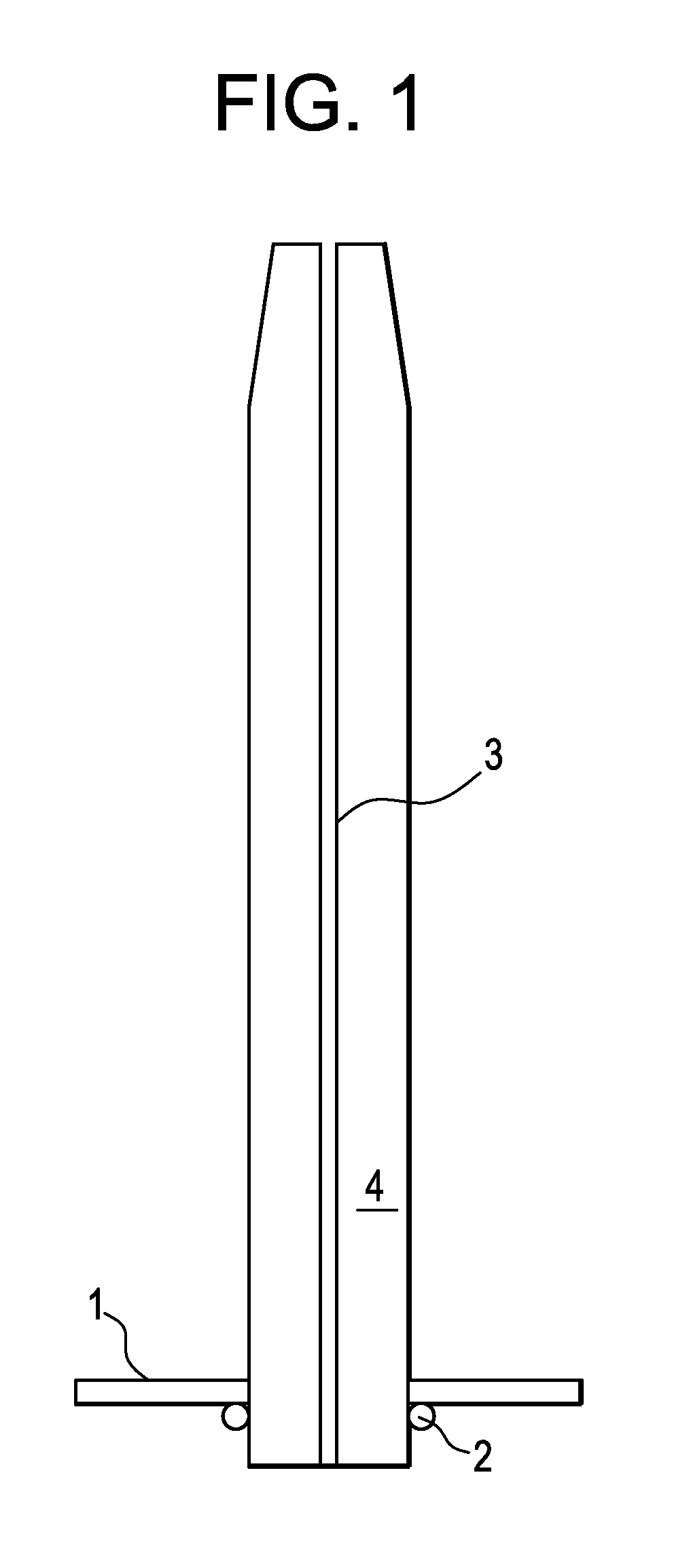
[0039]This example pertains to the installation of a rock bolt assembly into rock of an to underground structure and comprises the following steps.[0040]1. A hole of suitable diameter and length is drilled into rock;[0041]2. Inserting a chuck protrusion into the upper end of the rock bolt assembly and fitting bearing plates onto the assembly; and[0042]3. Engaging the rock bolt assembly into the drilled hole and, using the drill head, hammering the rock bolt assembly into the hole until it is fully inserted. The rock bolt assembly will become secured in the drilled hole due to an interference fit. Once the rock bolt assembly is in place, the unit is upon contact with water in the manner described above, i.e., the soap and salt will be dissolved by the water, which in turn will permit the water-activated expandable hydrophobic pre-polymeric resin to react with water and seal both the annular space of the rock bolt assembly and any fissures present in the rock.

example 3

[0043]After a Split Set roof bolt has been installed in the rock, the bolt can be waterproofed by the following method. First, prepare a soap tube unit with a water activated, expandable hydrophobic pre-polymeric and also a unit containing water. Then both units are slid up the center of the Split Set bolt and secured at the top of the bolt with use of a plug, such as balled rag or burlap. Then take a tube of our two component rigid foam, enter the nozzle of the tube into the opening of the Split Set bolt and seal around the opening with a rag or burlap, then dispense resin from the to tube to refusal (the resinous material has a 3+ second reaction time). Once finished, the nozzle and rag or burlap are removed. This procedure then waterproofs a Split Set bolt in-situ. The rigid foam induced into the bottom portion of the Split Set bolt will, depending upon its density, increase the pull out force required. Also of course the force required to insert the bolt will be higher. Having a...


PUM


Abstract

The present invention is directed to sealable rock bolts that prevent water leakage through the bolt, a kit containing portions of such bolts prior to assembly, installation, and use, and a method of using such sealable rock bolts. Such rock bolts are fastened in place in a roof, wall, or bottom of an underground region via pressure fitting or the like. The rock bolt contains a sealing unit that contains a liquid water activated, expandable hydrophobic pre-polymeric resin. The sealing unit has side, top, and bottom portions that are degradable by water to permit the resin to expand upon contact with water and to seal the bolt to prevent water passage through the bolt.

Description

[0001]This patent application claims priority under 35 U.S.C. 119(e) from U.S. provisional patent application Ser. No. 61 / 548,572 filed Oct. 18, 2011, entitled Rock Bolt Sealing System, and incorporated herein by reference in its entirety.FIELD OF INVENTION[0002]The present invention is directed to a technique and system for sealing rock bolts to prevent the leakage of water or other liquids after the rock bolt has been set in to place in the roof or wall of a mine, karst zone, or other underground structure. The invention also pertains to a sealable rock bolt, a rock bolt kit useful in the practice of the invention and a sealing unit to be inserted into the rock bolt to cause sealing.BACKGROUND OF THE INVENTION[0003]Rock bolts, sometimes referred to as friction rock stabilizers, are support mechanisms designed to be placed into a drilled hole or opening in the roof, side, or bottom of an underground structure where such bolts are anchored and sometimes tensioned to support the over...

Claims


Application Information

Patent Timeline
Patent Type & Authority Applications(United States)
IPC IPC(8): E21D21/00E21D20/02
CPCE21D20/026E21D21/008E21D21/004
Inventor SMITH, ERIC W.LIBENGOOD, HOMER D.
Owner SMITH ERIC W
Why Eureka
Try Eureka