Electrical junction box
- Summary
- Abstract
- Description
- Claims
- Application Information
AI Technical Summary
Benefits of technology
Problems solved by technology
Method used
Image
Examples
Embodiment Construction
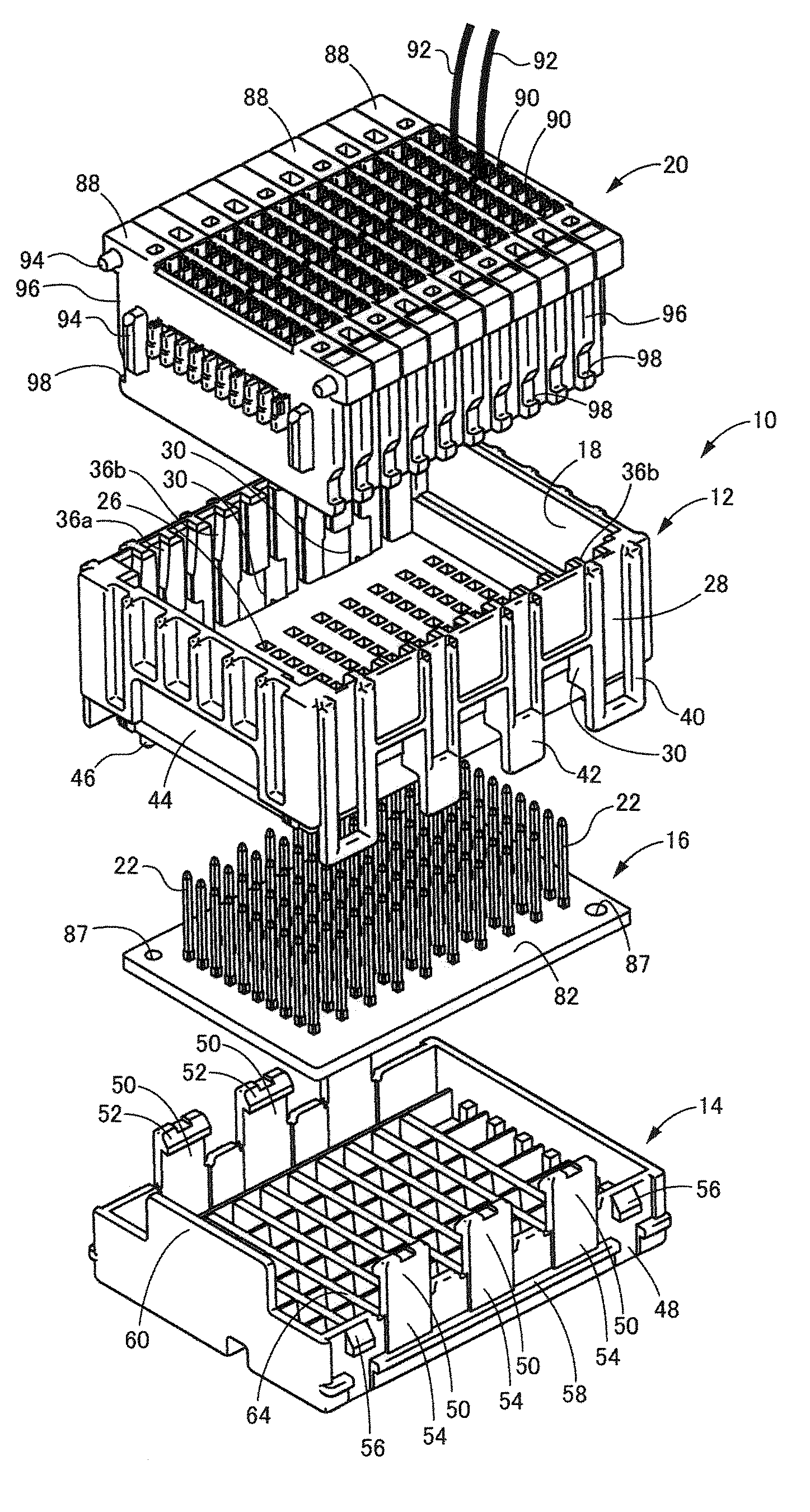
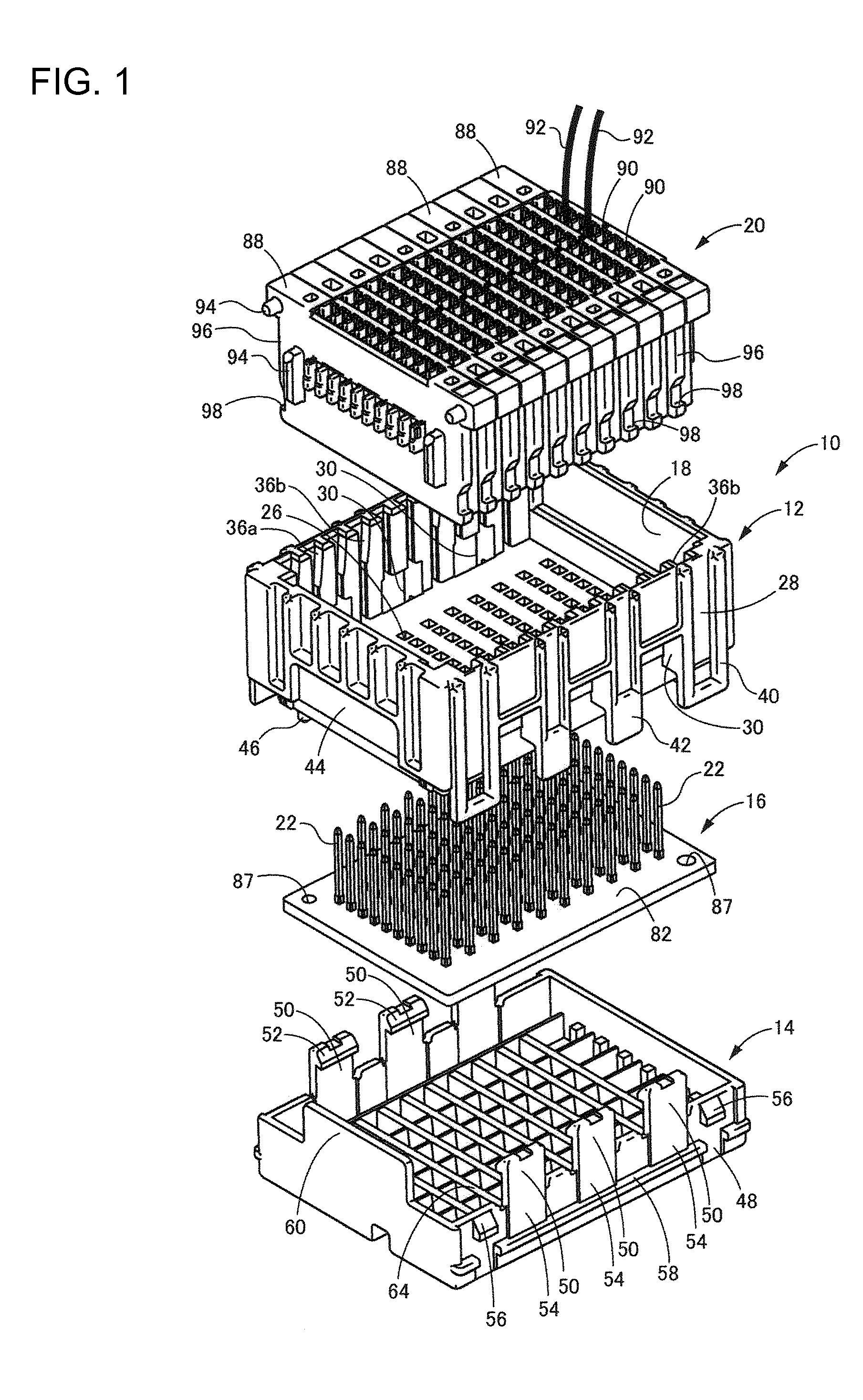
[0032]FIG. 1 shows an electrical junction box 10 according to a first embodiment of the invention. The electrical junction box 10 has a circuit board 16 housed between a first or upper case 12 and a second or lower case 14. A stacked connector 20 is housed in a receptacle 18 in the upper case 12 and can be connected to connection terminals 22 projecting from the circuit board 16. The terms upper and lower are used herein to refer to the orientation shown in FIG. 1.
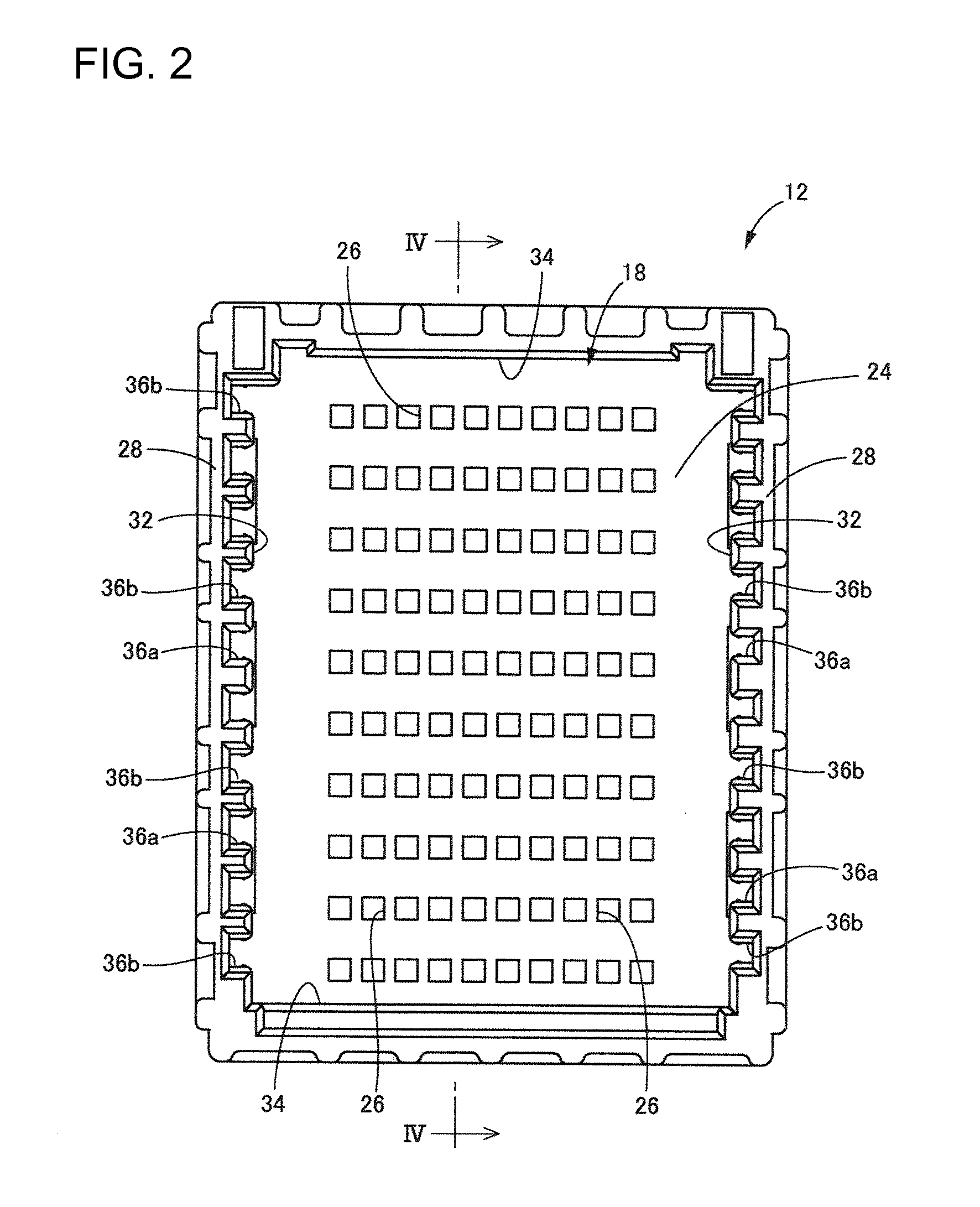
[0033]FIGS. 2 to 4 show the upper case 12. The upper case 12 is molded unitarily from synthetic resin to define a substantially elongated rectangular box that is open at the top. The receptacle 18 is a substantially rectangular void in the open top of the upper case 12.
[0034]The upper case 12 has a bottom wall 24 at the bottom of the receptacle 18 and terminal insertion holes 26 are formed in the bottom wall 24. In the present embodiment, ten terminal insertion holes 26 are formed in a row and are separated by a constant g...
PUM
 Abstract
Description
Claims
Application Information
 - R&D
- Intellectual Property
- Life Sciences
- Materials
- Tech Scout
- Unparalleled Data Quality
- Higher Quality Content
- 60% Fewer Hallucinations
Browse by: Latest US Patents, China's latest patents, Technical Efficacy Thesaurus, Application Domain, Technology Topic, Popular Technical Reports.
© 2025 PatSnap. All rights reserved.Legal|Privacy policy|Modern Slavery Act Transparency Statement|Sitemap|About US| Contact US: help@patsnap.com


