Stator unit of rotary electric machine and method for manufacturing stator unit of rotary electric machine

Pending Publication Date: 2021-09-16
HONDA MOTOR CO LTD
View PDF3 Cites 0 Cited by
  • Summary
  • Abstract
  • Description
  • Claims
  • Application Information

AI Technical Summary

Benefits of technology

[0010]According to the present invention, a degree of freedom in layout of a stator unit is

Problems solved by technology

When the rotary electric machine becomes excessively hot due to the heat generation, the output performance may be deteriorated.
However, in the stator unit of JP-A-2003-32964, since the stator unit is required to be arranged in the vicinity of the fixing member, an arrangement position of the stator unit is restricted.
Further, there

Method used


Image

  • Stator unit of rotary electric machine and method for manufacturing stator unit of rotary electric machine
  • Stator unit of rotary electric machine and method for manufacturing stator unit of rotary electric machine
  • Stator unit of rotary electric machine and method for manufacturing stator unit of rotary electric machine

Examples


Example

[0016]Hereinafter, a stator unit of a rotary electric machine according to an embodiment of the present invention will be described with reference to the accompanying drawings.

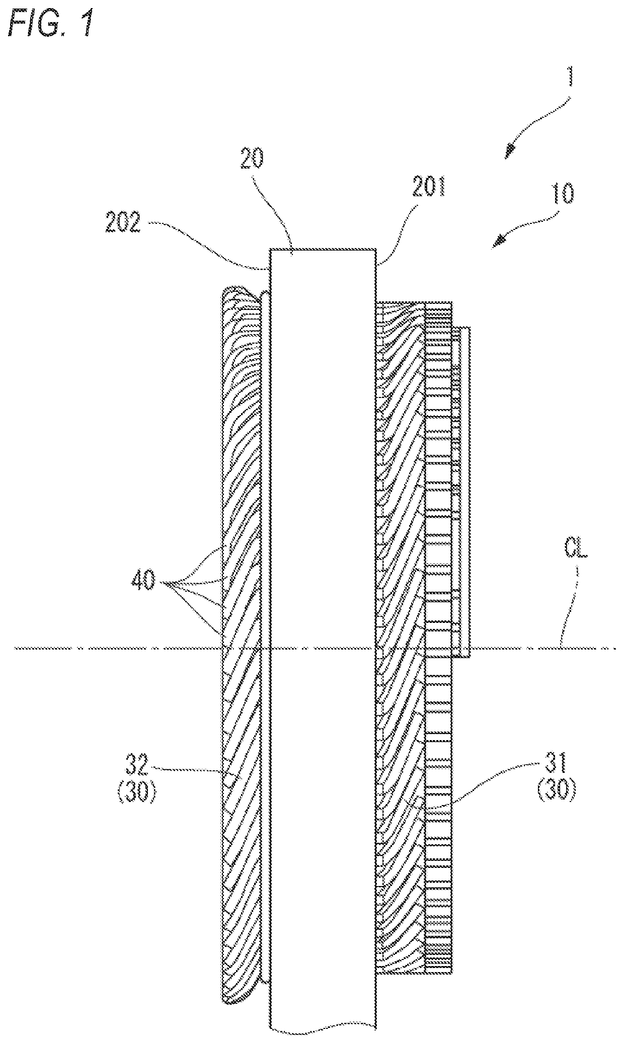
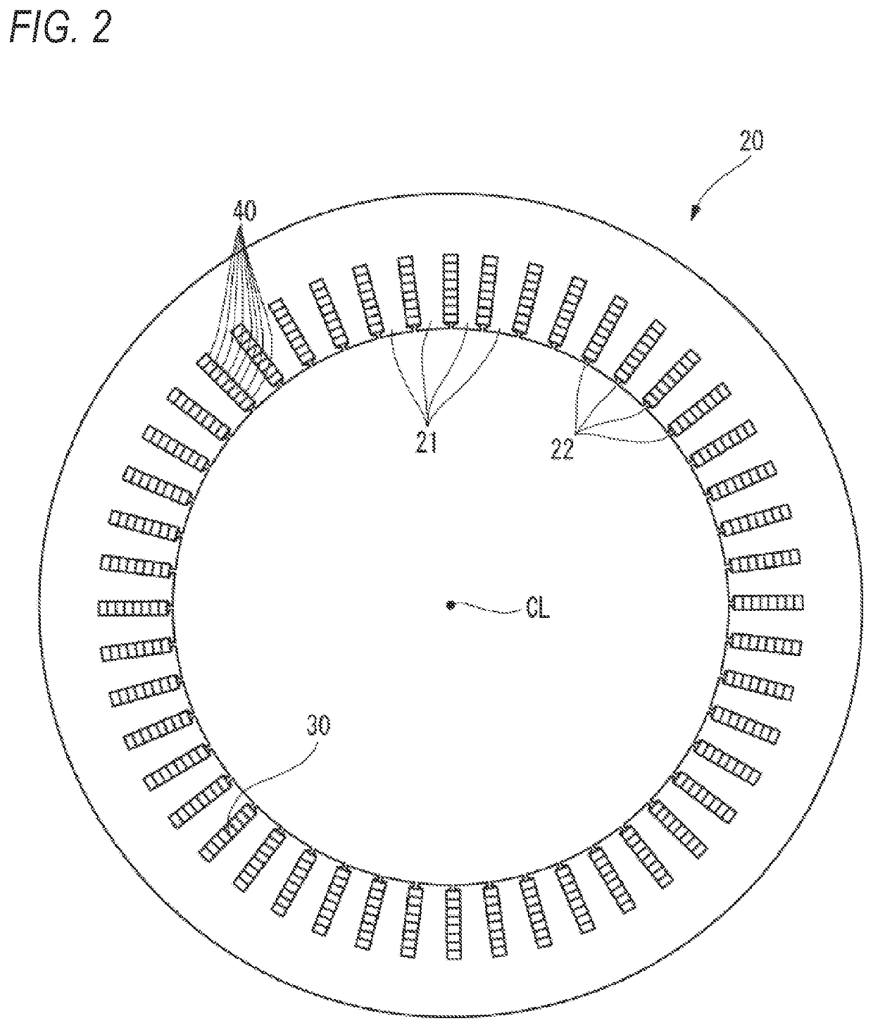
[0017]As shown in FIGS. 1 and 2, a stator unit 1 of a rotary electric machine according to the present embodiment includes a stator 10 having a substantially annular stator core 20 and a coil 30 assembled to the stator core 20, and a thermistor 50 (see FIG. 4) fixed to the coil 30.

[0018]In the present specification and the like, for the sake of simplicity and clarity, an axial direction, a radial direction, and a peripheral direction refer to directions with reference to a central axis CL of the stator 10 and the stator core 20. Further, an inner side in the axial direction refers to a central side of the stator 10 in the axial direction, and an outer side in the axial direction refers to a side away from the center of the stator 10 in the axial direction.

[0019]The stator core 20 has a substantially annular sh...


PUM


Abstract

A stator unit of a rotary electric machine includes a stator including a stator core and a coil, and a thermistor fixed to the coil. The stator core includes a plurality of teeth and a plurality of slots. The coil includes a plurality of segment conductors inserted into each of the plurality of slots. The segment conductor includes a leg portion and an oblique portion. The thermistor is fixed to the coil by being sandwiched between the oblique portion of a predetermined segment conductor and the oblique portion of a segment conductor which is adjacent to the predetermined segment conductor in a peripheral direction.

Description

CROSS-REFERENCE TO RELATED APPLICATIONS[0001]This application is based upon and claims the benefit of priority from prior Japanese patent application No. 2020-045570, filed on Mar. 16, 2020, the entire contents of which are incorporated herein by reference.TECHNICAL FIELD[0002]The present invention relates to a stator unit of a rotary electric machine mounted on an electric vehicle or the like, and a method for manufacturing a stator unit of a rotary electric machine.BACKGROUND ART[0003]In the related art, a rotary electric machine such as an electric motor and a generator is mounted on an electric vehicle such as a hybrid vehicle, a battery drive vehicle, a fuel cell vehicle. As a rotary electric machine mounted on an electric vehicle or the like, there is known a rotary electric machine including a stator having a substantially annular stator core in which a plurality of slot portions are formed on an inner peripheral surface thereof and a coil inserted into the plurality of slot ...

Claims


Application Information

Patent Timeline
IPC IPC(8): H02K11/25H02K3/48H02K1/16H02K15/06H01C7/00
CPCH02K11/25H02K3/48H01C7/008H02K15/062H02K1/16H02K1/165H02K3/12H02K3/50H02K15/026H02K15/064
Inventor NISHIDA, ATSUSHI
Owner HONDA MOTOR CO LTD
Why Eureka
Try Eureka