Video encoding apparatus and a video decoding apparatus

Active Publication Date: 2014-07-03
KK TOSHIBA
View PDF13 Cites 0 Cited by
  • Summary
  • Abstract
  • Description
  • Claims
  • Application Information

AI Technical Summary

Benefits of technology

[0009]It is an object of the present invention to provide a video encoding apparatus and a video decoding apparatus which reduce additional informatio

Problems solved by technology

Therefore, degrees of freedom for calculat

Method used


Image

  • Video encoding apparatus and a video decoding apparatus
  • Video encoding apparatus and a video decoding apparatus
  • Video encoding apparatus and a video decoding apparatus

Examples


Embodiment Construction

[0026]There will now be explained embodiments of the present invention referring to drawings.

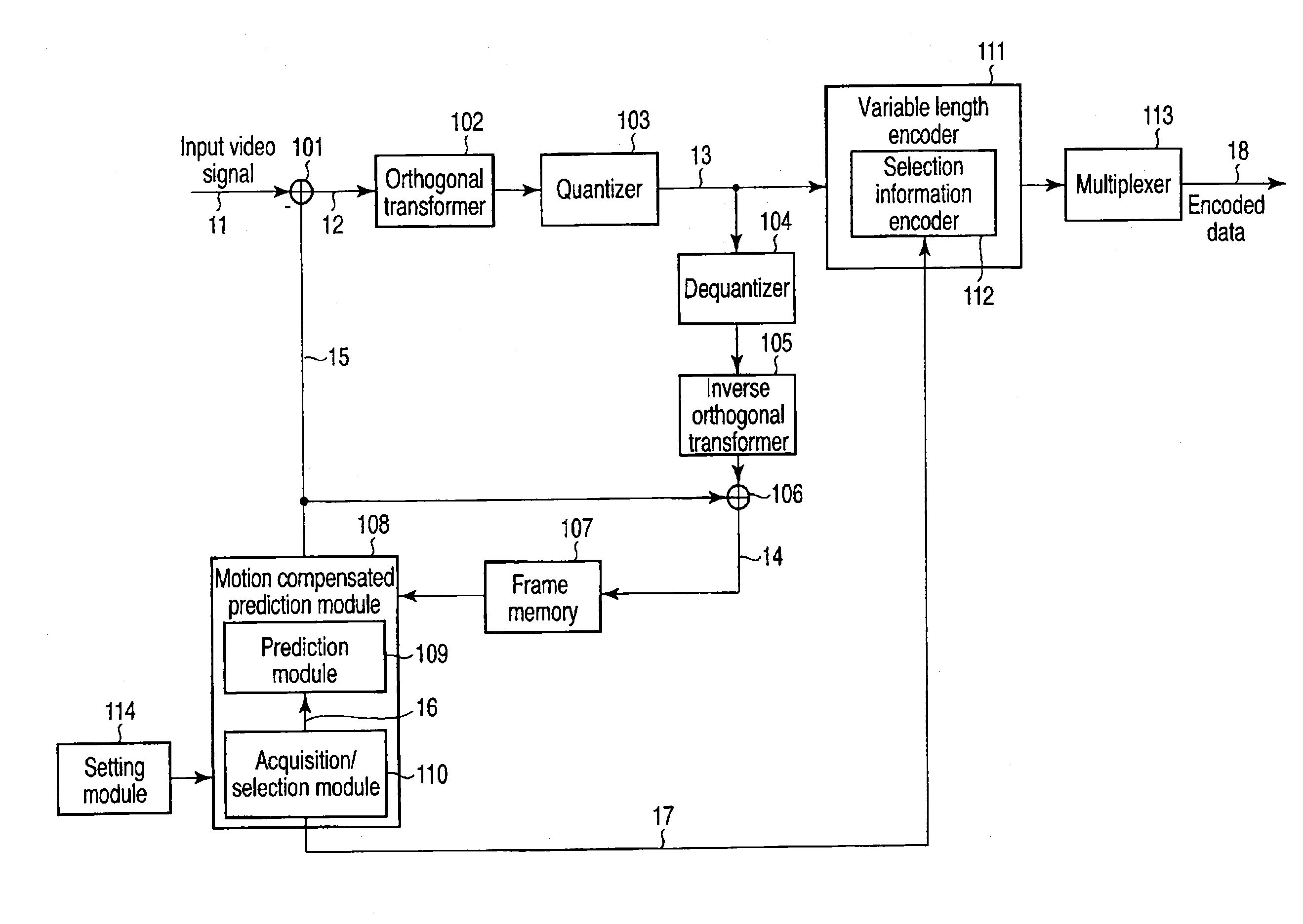
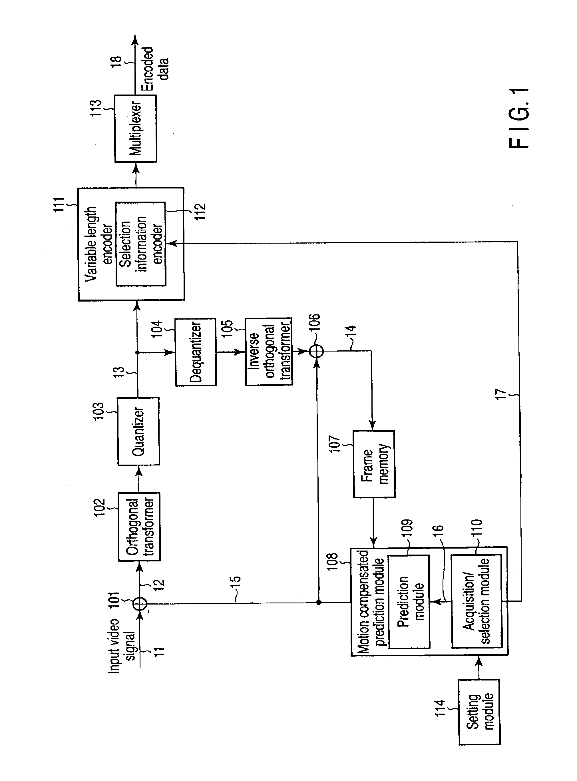
[0027]A video encoding apparatus related to an embodiment is described with reference to FIG. 1 hereinafter. A subtracter 101 calculates a difference between an input video signal 11 and a predictive coded video signal 15, and output a prediction error signal 12. The output terminal of the subtracter 101 is connected to a variable length encoder 111 through an orthogonal transformer 102 and a quantizer 103. The orthogonal transformer 102 orthogonal-transforms a prediction error signal 12 from the subtracter 101, and the quantizer 103 quantizes an orthogonal transformation coefficient and outputs quantization orthogonal transformation coefficient information 13. The variable length encoder 111 performs variable length encoding on the quantization orthogonal transformation coefficient information 13 from the quantizer 103.

[0028]The output terminal of the quantizer 103 is connected to an adder ...


PUM


Abstract

A video encoding apparatus is a video encoding apparatus for subjecting a video image to motion compensated prediction coding, comprising an acquisition module to acquire available blocks of blocks having motion vectors from encoded blocks adjacent to a to-be-encoded block and number of the available blocks, an acquisition/selection module to select one selection block from the encoded available blocks, a selection information encoder to encode selection information specifying the selection block using a code table corresponding to the number of available blocks, and an image encoder to subject the to-be-encoded block to motion compensated prediction coding using a motion vector of the selection block.

Description

CROSS-REFERENCE TO RELATED APPLICATIONS[0001]This is a Continuation-In-Part application of Continuation application Ser. No. 13 / 325,856, filed Dec. 14, 2011, which is a Continuation application of PCT Application No. PCT / JP2009 / 061130, filed Jun. 18, 2009, which was published under PCT Article 21(2) in Japanese, and the entire contents of which are incorporated herein by reference.BACKGROUND OF THE INVENTION[0002]1. Field of the Invention[0003]The present invention relates to a video encoding apparatus and a video decoding apparatus which derive a motion vector from an encoded and decoded image and perform a motion compensated prediction.[0004]2. Description of the Related Art[0005]There is a motion compensated prediction as one of techniques used for encoding a video image.[0006]In the motion compensated prediction, a video encoding apparatus acquires a motion vector using a to-be-encoded image to be newly encoded and a local decoded image already generated and generates a predicti...

Claims


Application Information

Patent Timeline
IPC IPC(8): H04N19/583
CPCH04N19/00733H04N19/46H04N19/13H04N19/593H04N19/463H04N19/91H04N19/51H04N19/513H04N19/176
Inventor ASAKA, SAORICHUJOH, TAKESHITANIZAWA, AKIYUKIYASUDA, GOKIWADA, NAOFUMIWATANABE, TAKASHI
Owner KK TOSHIBA
Why Eureka
Try Eureka