Trolley Braking System

a technology of braking system and trolley, which is applied in the direction of transportation and packaging, rope railways, roads, etc., can solve the problems of inconsistent and/or abrupt application of braking force, and achieve the effect of smooth increase of braking for

Inactive Publication Date: 2013-09-19
BOREN DANIEL BLAIR +4
View PDF3 Cites 19 Cited by
  • Summary
  • Abstract
  • Description
  • Claims
  • Application Information

AI Technical Summary

Benefits of technology

[0007]The braking resistance provided to the braking block, and consequently to the trolley, results from the resistance to the piston's movement by the accumulated compressed air created inside the cylinder as the pneumatic piston is drawn further into a cylinder by the braking cable, as the trolley travels forward towards the landing platform. The resulting compressed air

Problems solved by technology

The friction surface is therefore subject to wear and other conditions wh

Method used


Image

  • Trolley Braking System
  • Trolley Braking System
  • Trolley Braking System

Examples


Embodiment Construction

[0021]It will be readily understood that the components of the present invention, as generally described and illustrated in the drawings herein, could be arranged and designed in a wide variety of different configurations. Thus, the following more detailed description of the embodiments of the system and method of the present invention, as represented in the drawings, is not intended to limit the scope of the invention, as claimed, but is merely representative of various embodiments of the invention. The illustrated embodiments of the invention will be best understood by reference to the drawings, wherein like, parts are designated, by like numerals throughout.

[0022]While a suspended cable or rope may provide the basis for an amusement ride, other uses are also contemplated, including ski lifts, gondolas, aerial trams, and suspended cable evacuation systems, such as oil derrick evacuation systems.

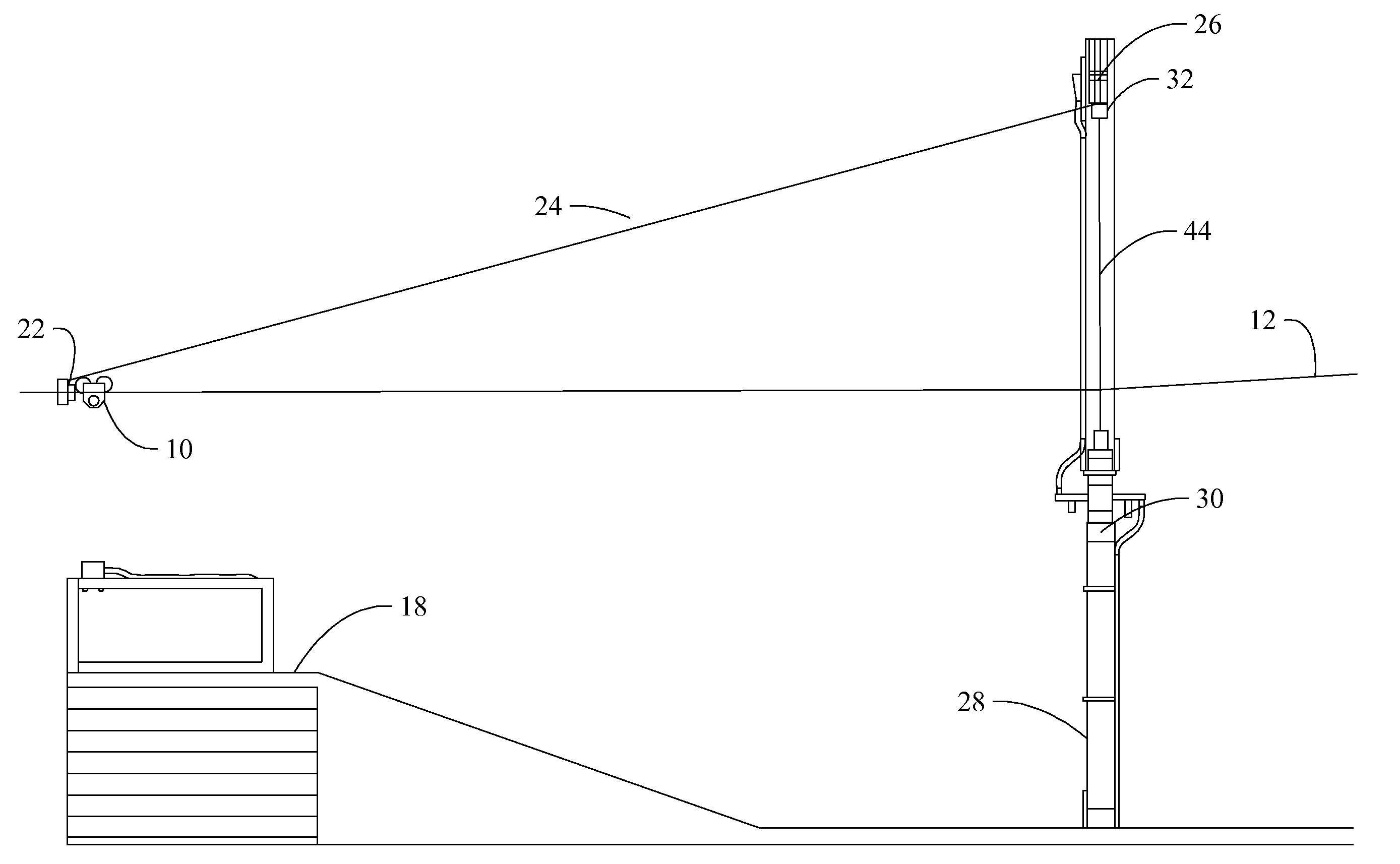
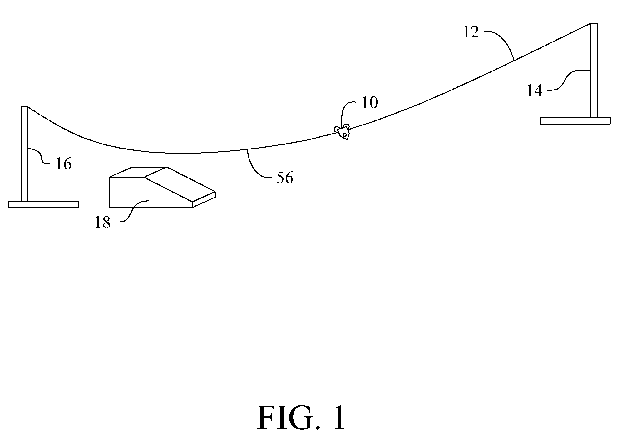
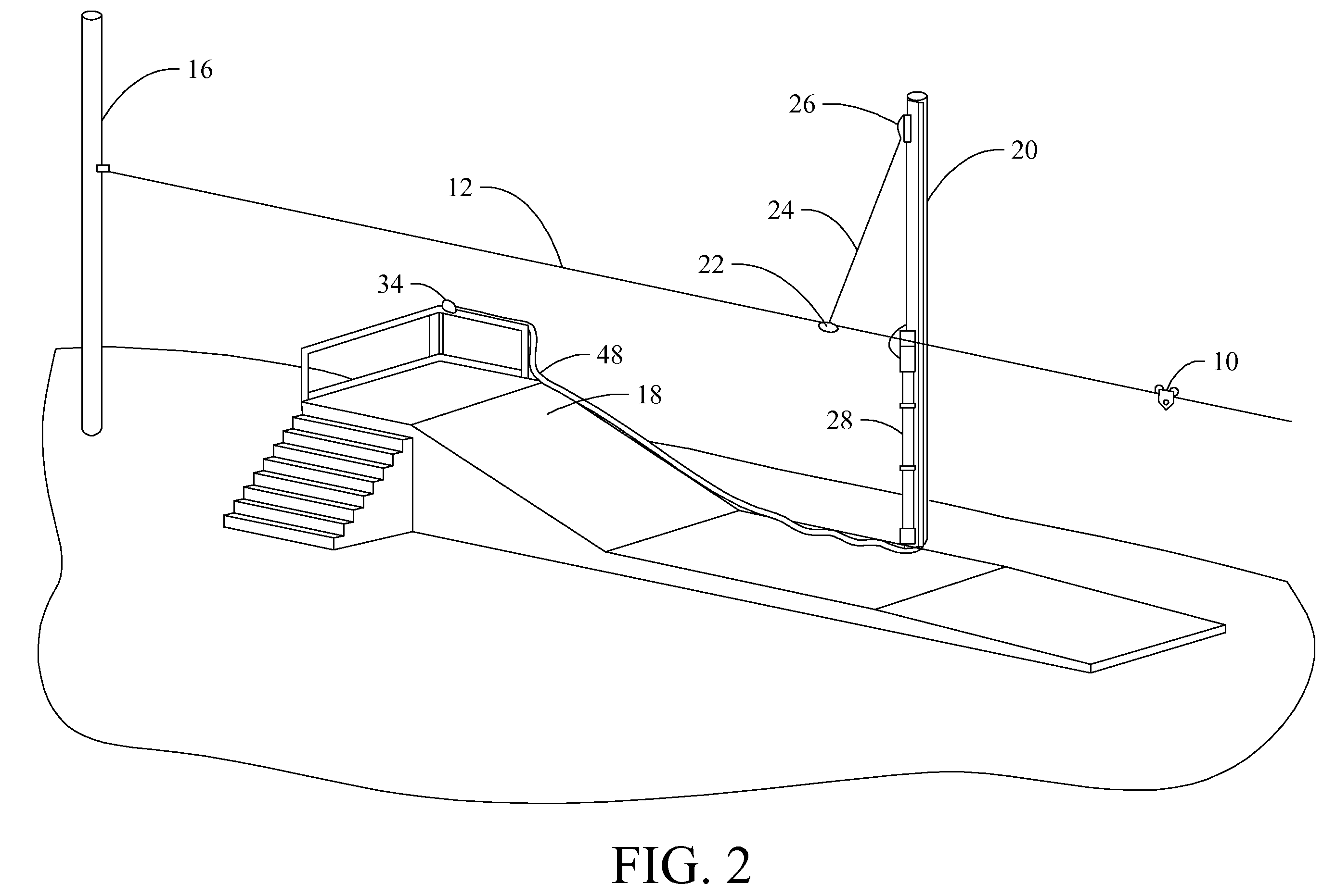
[0023]Referring to FIG. 1, in a typical zipline configuration, a trolley 10 is used for...


PUM


Abstract

A trolley braking system for smoothly reducing the speed of a rider supported by a harness on a cable or rope approaching a landing platform comprises a cylinder having a closed end and a piston slidably mounted in the interior. A braking cable is secured to the piston and routed through an opening in the closed end of the cylinder to a braking block, which is slidably mounted on the cable between the trolley and the landing platform. The system may also may also include a relief valve to release compressed air from the cylinder, so that the braking force may be controlled.

Description

BACKGROUND[0001]1. The Field of the Invention[0002]The present invention is directed to a method and device for providing braking for a trolley traveling on a suspended cable or rope system.[0003]2. The Background Art[0004]Many prior art braking devices used to control the speed of trolleys provide braking force by contact between the cable or a pulley on the trolley with a friction surface on the trolley. The friction surface is therefore subject to wear and other conditions which may result in inconsistent and / or abrupt application of braking force. Also, it is desirable to ensure that the braking force is applied at the proper time for effectiveness and safety. Many such braking devices depend upon proper operation by the rider for satisfactory results.BRIEF SUMMARY OF THE INVENTION[0005]In view of the foregoing, in accordance with the invention as embodied and broadly described herein, a method and apparatus are disclosed for providing braking force to a trolley used to support ...

Claims


Application Information

Patent Timeline
IPC IPC(8): B61K7/02B61B7/00
CPCA63G21/20B61B7/00B61H9/02F16D63/008
Inventor BOREN, DANIEL BLAIREPSTEIN, BRETT J.HAAS, JOEL C.MILLER, JESSE E.PRUS, GARY P.
Owner BOREN DANIEL BLAIR
Why Eureka
Try Eureka