Voltage regulator

Inactive Publication Date: 2013-09-19
SEIKO INSTR INC
View PDF25 Cites 6 Cited by
  • Summary
  • Abstract
  • Description
  • Claims
  • Application Information

AI Technical Summary

Benefits of technology

[0013]The voltage regulator including a rush current prevention circuit of the present invention is able to reduce the consumption c

Problems solved by technology

The conventional technique, however, has a problem that, after the output voltage starts up, a current

Method used


Image

  • Voltage regulator
  • Voltage regulator
  • Voltage regulator

Examples


first embodiment

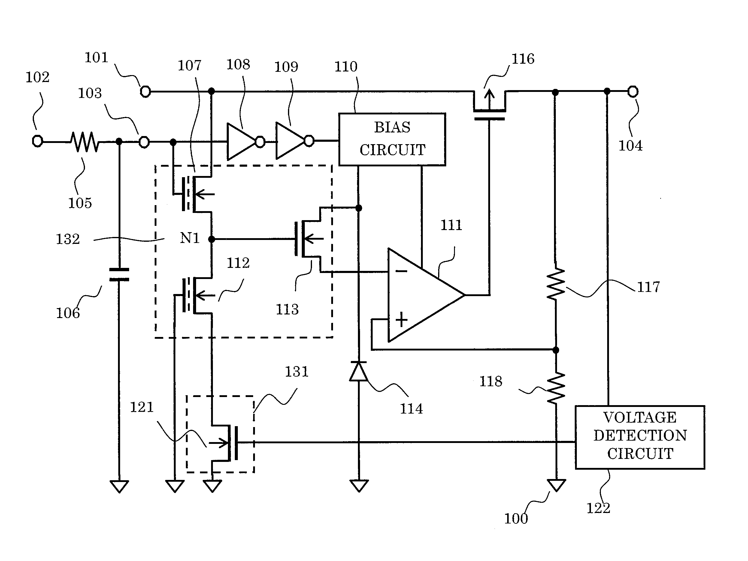
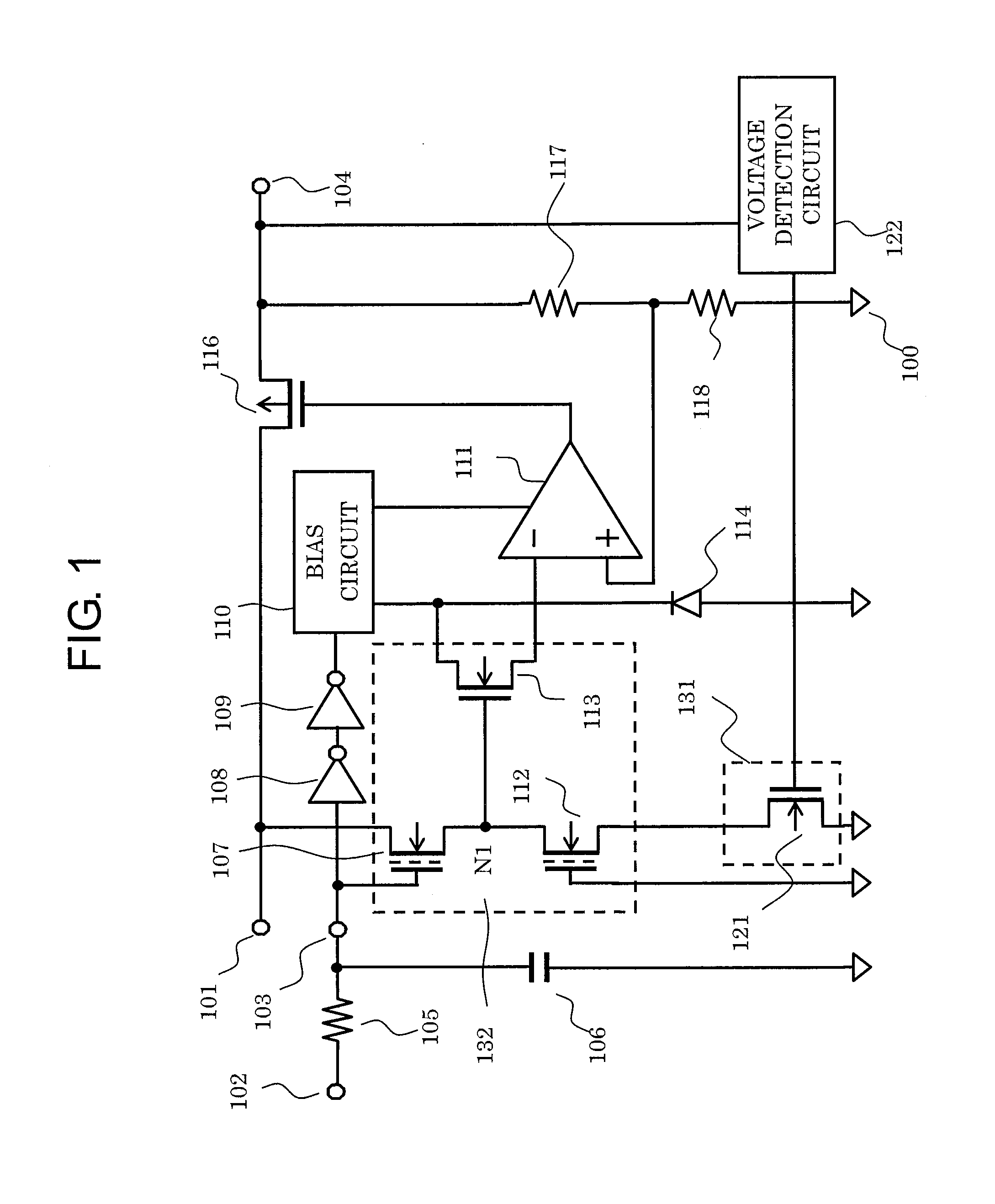
[0018]Referring to FIG. 1, there is illustrated a circuit diagram of a voltage regulator according to a first embodiment.

[0019]The voltage regulator of the first embodiment includes a bias circuit 110, an amplifier 111, a voltage detection circuit 122, Nch depression transistors 107 and 112, NMOS transistors 113 and 121, a PMOS transistor 116, a diode 114, resistors 105, 117, and 118, a capacitor 106, inverters 108 and 109, a ground terminal 100, an output terminal 104, a supply terminal 101, a CE terminal 103, and an EN terminal 102. A switch circuit 131 includes the NMOS transistor 121. A rush current prevention circuit 132 includes the Nch depression transistors 107 and 112 and the NMOS transistor 113.

[0020]Subsequently, the connections of the voltage regulator of the first embodiment will be described. The resistor 105 is connected between the EN terminal 102 and the CE terminal 103. The capacitor 106 is connected between the CE terminal 103 and the ground terminal 100. The Nch ...

second embodiment

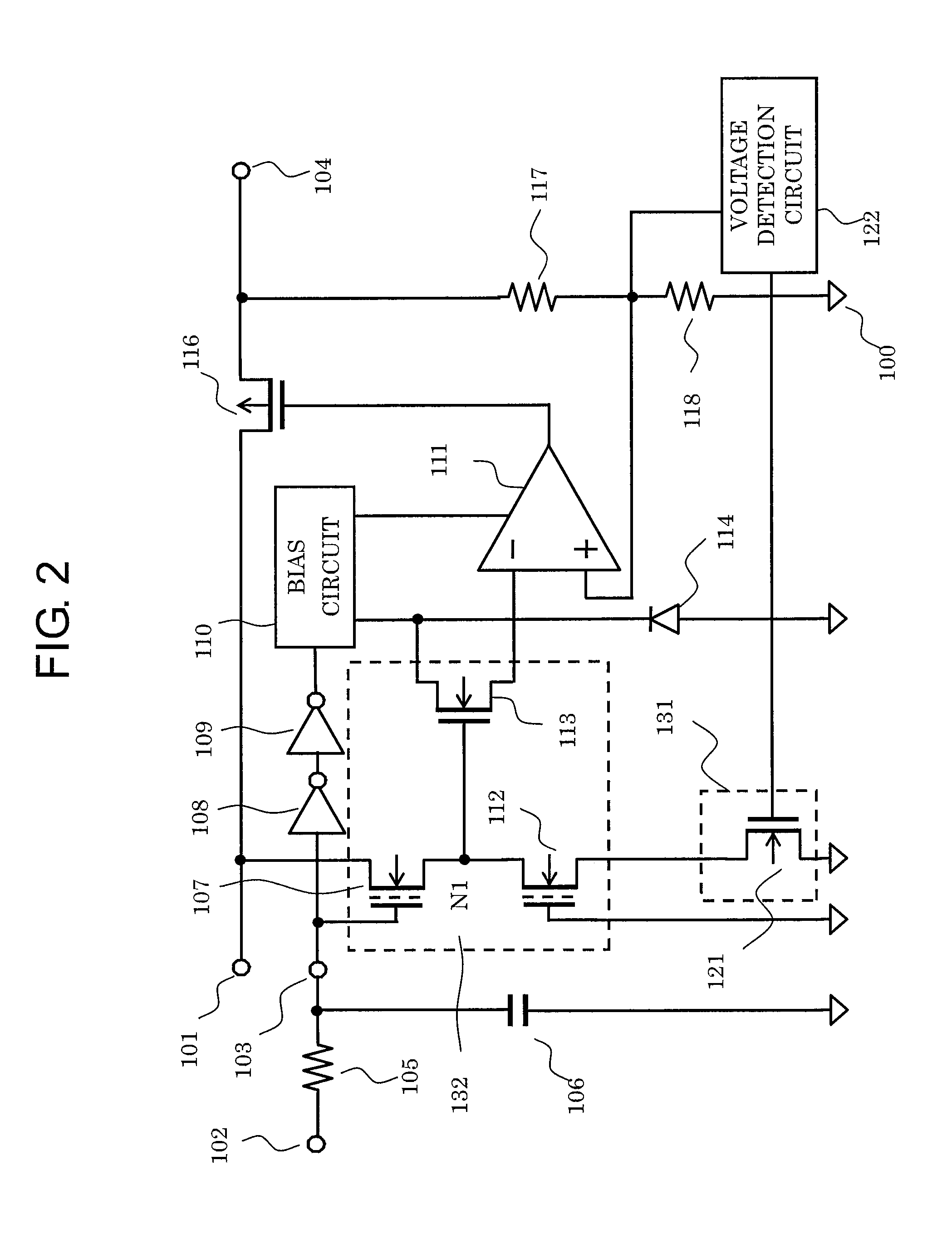
[0028]FIG. 2 is a circuit diagram illustrating a voltage regulator of a second embodiment. The circuit differs from the circuit illustrated in FIG. 1 in that the voltage detection circuit 122 is connected to a connection point between the resistor 117 and the resistor 118. Also in this configuration, it is possible to detect a voltage obtained by dividing the output voltage VOUT by the resistors 117 and 118 and to output a signal which turns off the NMOS transistor 121. In addition, it is possible to prevent the current from flowing from the Nch depression transistor 112, thereby achieving low power consumption.

[0029]Although the voltage which is detected by the voltage detection circuit 122 as an output voltage VOUT is the voltage at the connection point between the resistor 117 and the resistor 118 in this embodiment, the resistor circuit may be modified appropriately so as to take out a desired voltage.

[0030]Moreover, although the NMOS transistor 121 is used as the switch circuit...


PUM


Abstract

In a voltage regulator having: a reference voltage generation circuit which generates a reference voltage; an amplifier which amplifies and outputs a difference between the reference voltage and a divided voltage obtained by dividing a voltage output from an output transistor and controls a gate of the output transistor; an external terminal which receives a signal which externally turns on/off a circuit; and a start-up circuit which transmits the reference voltage to the amplifier, the improvement including: a voltage detection circuit which detects the voltage output from the output transistor; and a switch circuit which is connected to the start-up circuit and interrupts a current which flows through the start-up circuit in response to a signal from the voltage detection circuit.

Description

RELATED APPLICATIONS[0001]This application claims priority under 35 U.S.C. §119 to Japanese Patent Application No. 2012-055921 filed on Mar. 13, 2012, the entire content of which is hereby incorporated by reference.BACKGROUND OF THE INVENTION[0002]1. Field of the Invention[0003]The present invention relates to a rush current prevention circuit of a voltage regulator.[0004]2. Description of the Related Art[0005]A conventional voltage regulator will be described below. FIG. 3 is a circuit diagram illustrating the conventional voltage regulator.[0006]The conventional voltage regulator includes a bias circuit 110, an amplifier 111, Nch depression transistors 107 and 112, an NMOS transistor 113, a PMOS transistor 116, a diode 114, resistors 105, 117, and 118, a capacitor 106, inverters 108 and 109, a ground terminal 100, an output terminal 104, a supply terminal 101, a CE terminal 103, and an EN terminal 102.[0007]If a power-supply voltage VDD is applied to the supply terminal 101 and a ...

Claims


Application Information

Patent Timeline
IPC IPC(8): G05F1/10
CPCG05F1/10G05F1/575
Inventor UEHARA, OSAMU
Owner SEIKO INSTR INC
Why Eureka
Try Eureka