Switching power source apparatus

Inactive Publication Date: 2007-09-13
SEIKO INSTR INC
View PDF6 Cites 71 Cited by
  • Summary
  • Abstract
  • Description
  • Claims
  • Application Information

AI Technical Summary

Benefits of technology

[0022] In the switching power supply circuit according to the present invention, it is possible to reduce the consumption current of the

Problems solved by technology

Accordingly, in the case where the switching frequency is low, an excessive current is allowed to flow

Method used


Image

  • Switching power source apparatus
  • Switching power source apparatus
  • Switching power source apparatus

Examples


Example

[0029] Subsequently, a description will be given of the best mode for carrying out the present invention with reference to the drawings.

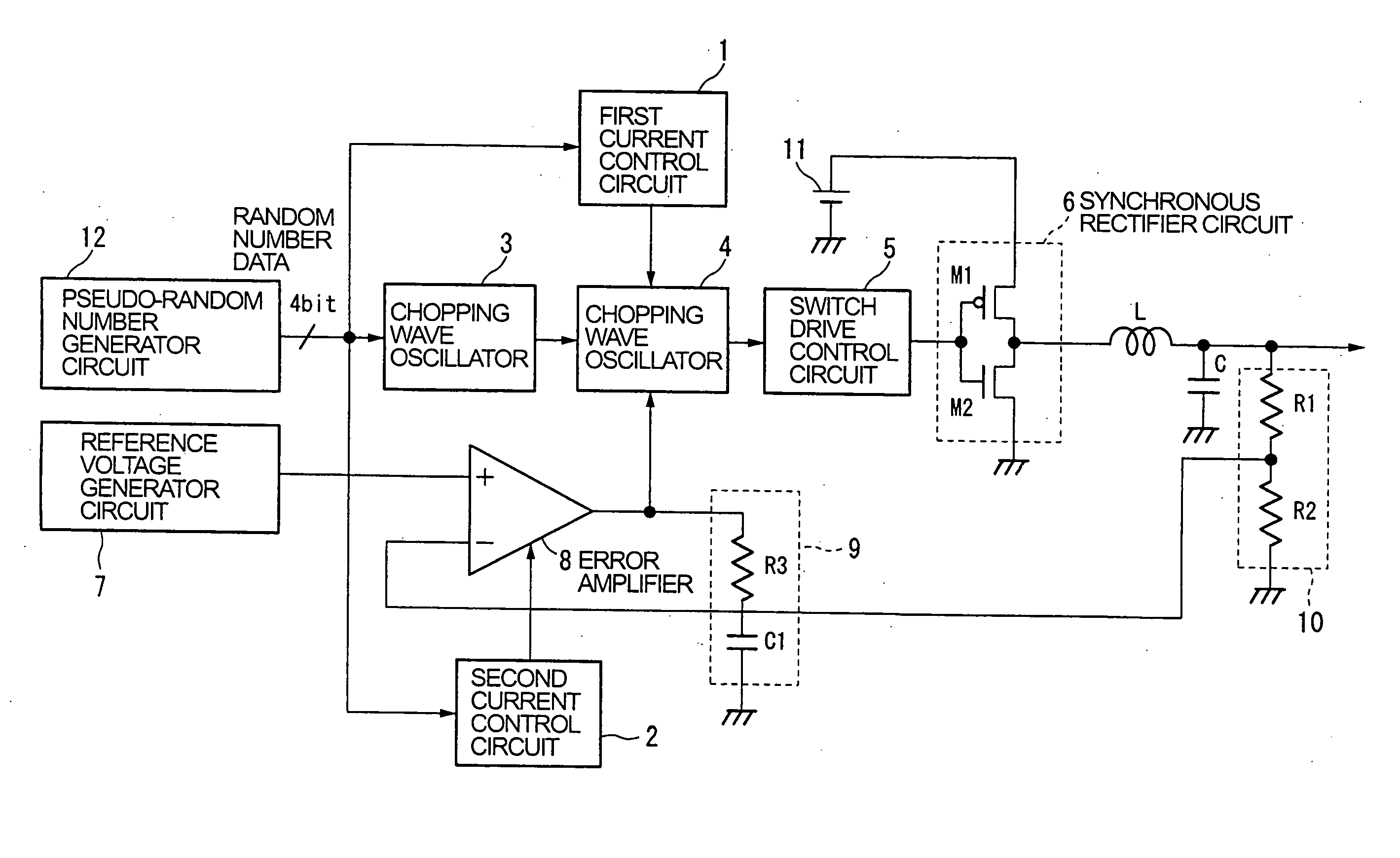
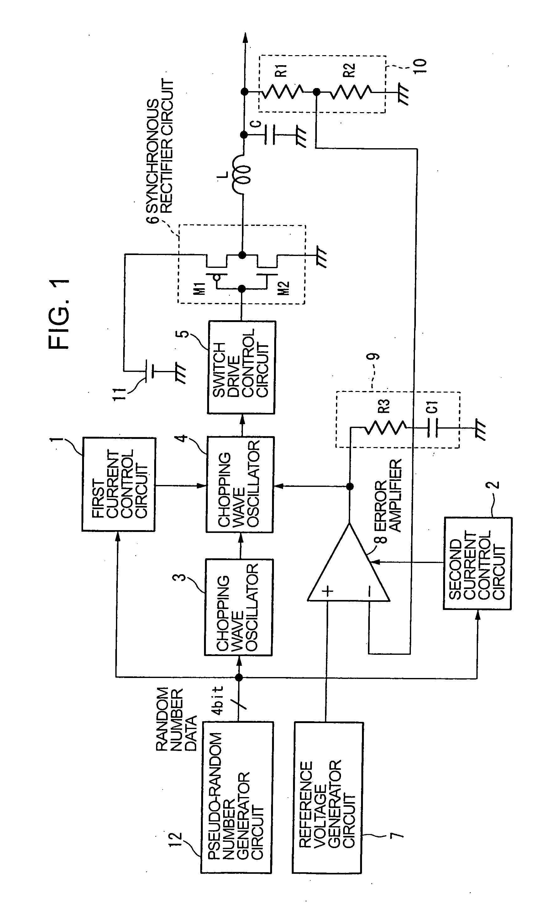
[0030]FIG. 1 is a diagram showing the structural example of a switching power supply device (DC / DC converter) according to the present invention.

[0031] The switching power supply device shown in FIG. 1 includes, as in the conventional switching power supply device shown in FIG. 6, a pseudo-random number generator circuit 12, a chopping wave oscillator 3, a PWM comparator 4, a switch drive control circuit 5, a synchronous rectifier circuit 6 that is made up of a PMOS transistor M1 and an NMOS transistor M2 which are switching elements, an external inductor L, an external capacitor C, a reference voltage generator circuit 7, an error amplifier 8, a stabilizer circuit 9 that is made up of a resistor R3 and a capacitor C1, and an output voltage detector circuit 10 that is made up of resistors R1 and R2. The circuit elements added in this circuit are a...


PUM


Abstract

There is provided a switching power supply device which is capable of reducing an influence of noises and also reducing a consumption current of a control circuit. A pseudo-random number generator circuit (12) generates random number data for determining frequencies of switching signals of MOS transistors (M1) and (M2). A chopping wave oscillation frequency (a frequency of a switching signal) of a chopping wave oscillator (3) randomly changes according to the random number data that is generated by the pseudo-random number generator circuit (12). A current control circuit (1) and a current control circuit (2) control consumption currents that flow in the chopping wave oscillator (3) and an error amplifier (8) according to a change (a change in the frequency of the switching signal) in the random number data that is generated by the pseudo-random number generator circuit (12).

Description

TECHNICAL FIELD [0001] The present invention relates to a switching power supply device for outputting a DC voltage with a given voltage value, and more particularly, to a switching power supply device that is capable of controlling a frequency of a switching signal of a switching element at random, and controlling a consumption current that flows in a given circuit section (such as an error amplifier) according to the frequency of the switching signal which is controlled at random. BACKGROUND ART [0002] Up to now, a switching power supply device (for example, DC / DC converter) of a pulse width modulation (PWM) control system is employed as an internal power supply of diverse electronic devices since the switching power supply device is capable of supplying a DC power supply with a stable voltage value. [0003] However, noises of a high frequency enter an electronic circuit from the switching power supply device, and such noises frequently induce the malfunction of the electronic devi...

Claims


Application Information

Patent Timeline
IPC IPC(8): G05F1/00
CPCH02M3/156H02M1/44
Inventor OKA, TOMOHIRO
Owner SEIKO INSTR INC
Why Eureka
Try Eureka