Device for Reading Assay Results on Test Carrier

a technology for reading devices and test strips, applied in measurement devices, instruments, scientific instruments, etc., can solve problems such as the sensitive reading of final results, and achieve the effect of avoiding interference and avoiding the influence of undesired ligh

Inactive Publication Date: 2013-09-19
ABON BIOPHARM HANGZHOU
View PDF6 Cites 10 Cited by
  • Summary
  • Abstract
  • Description
  • Claims
  • Application Information

AI Technical Summary

Benefits of technology

[0011]The present invention provides a device capable of avoiding the interference of the undesired light with the photodetector, and irradiating the light reflected or transmitted from the assay strip or the test carrier onto the photodetector as much as possible; and especially enabling the photodetector to detect the light effectively reflected or transmitted from the test carrier and reflecting the variation of the signals in the detecting zones and / or controlled zones, while avoiding the influence from undesired light. Generally, when performing an assay by using liquid-delivering carrier, the liquid sample is first applied on the carrier, and the assay result is read by using a reading device. In one preferred example, the assay result is read by using an optical system.
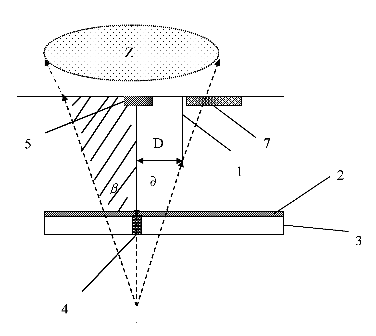
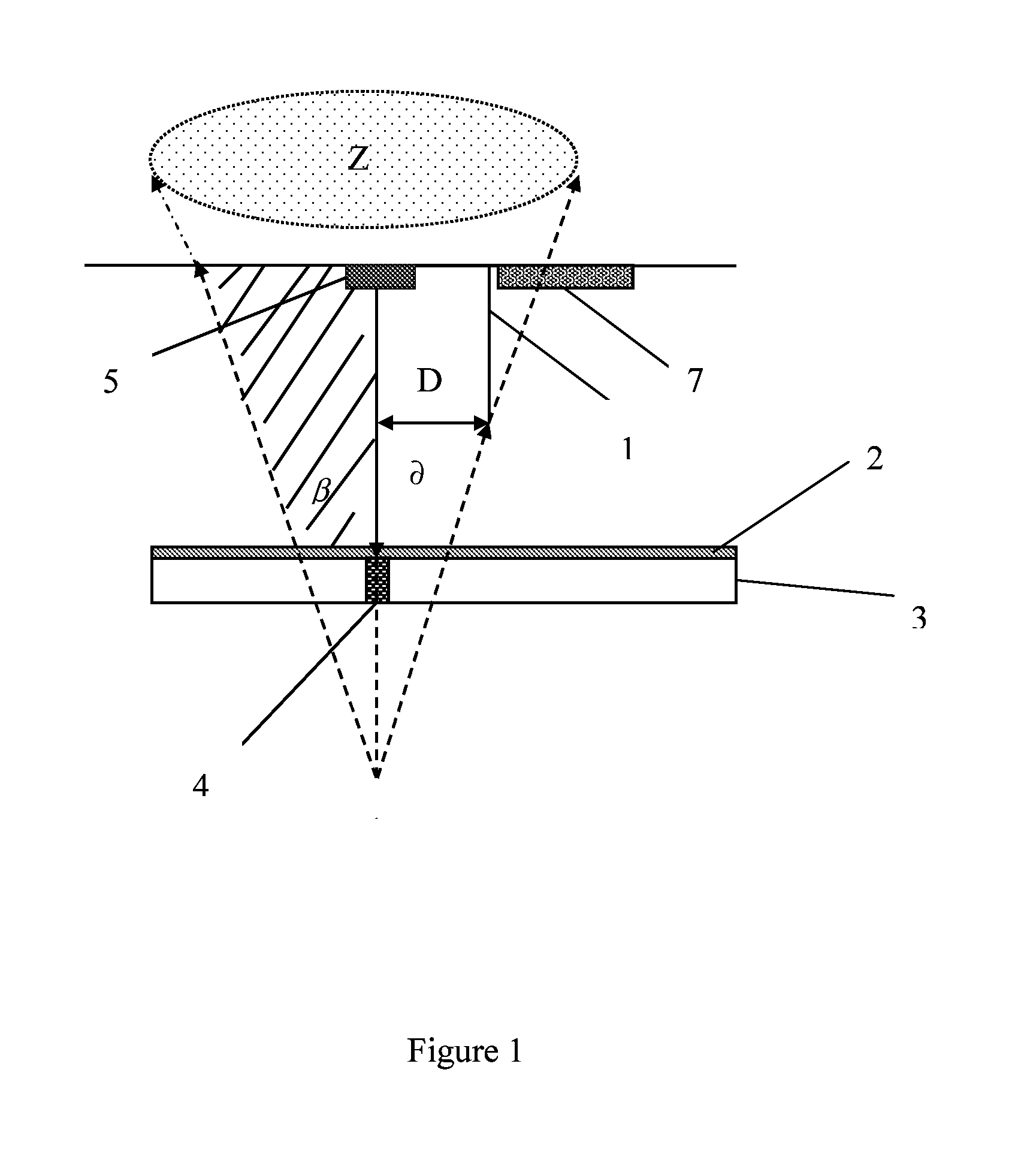
[0014]In another preferred embodiment, the light-blocking element is positioned in an area in which the light emitted from the light-emitting element is irradiated and mirror reflection is occurred on the test carrier. In this way, part or all of the light mirror-reflected from the test carrier can be blocked and will not be detected by the photodetector, and inaccurate reading for the assay result on the test carrier can be avoided.
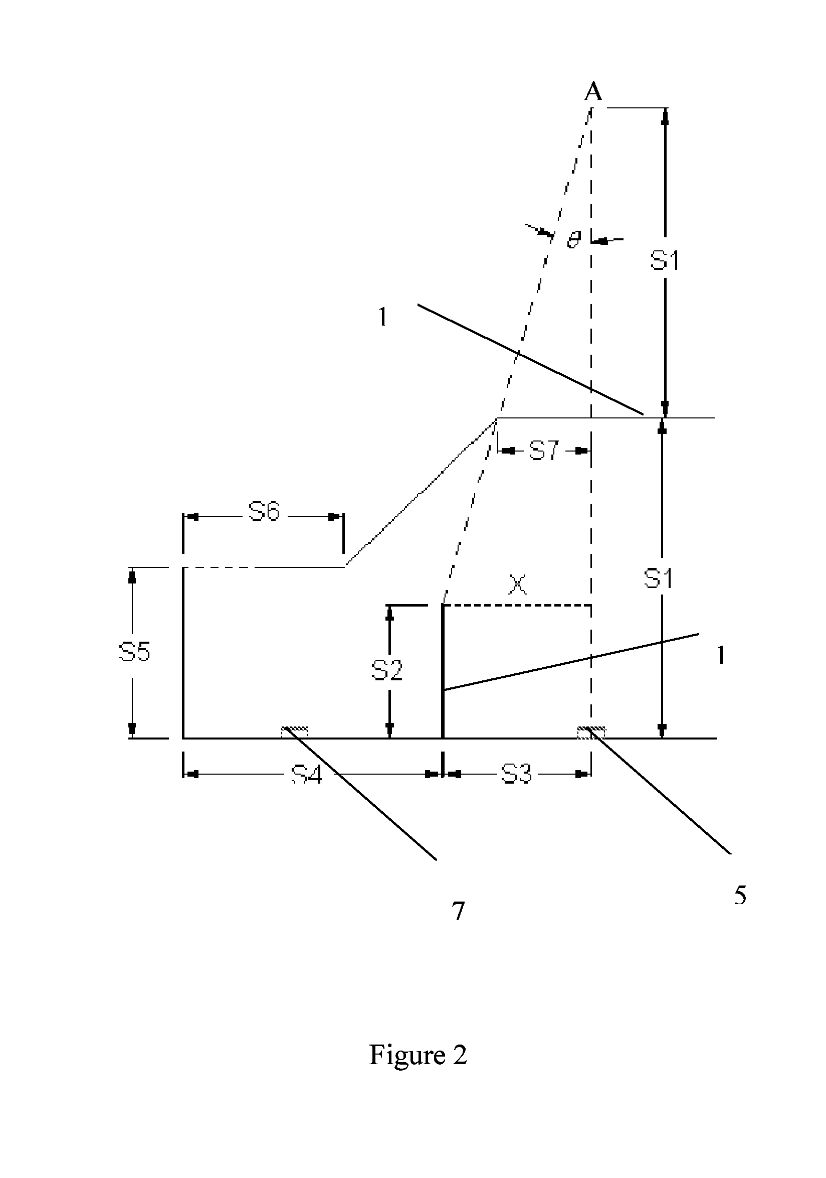
[0015]In another preferred embodiment, the device can further include a window through which the light emitted from the light-emitting element is irradiated onto the test carrier, where the positions of the light-emitting element, the light-blocking element and the window meet the function ofS3≧S7S1×(2×S1-S2),where S1 represents the vertical distance between the light-emitting element and the window; S2 represents the vertical height of the light-blocking element; S3 represents the vertical distance between the light-blocking element and the light-emitting element; and S7 represents the length of the window. In this way, the light mirror-reflected from the testing strip can be effectively prevented from being irradiated onto the photodetector, thereby reducing the interference of the mirror-reflected light with the final test result. In one preferred embodiment, the positions of the light-emitting element, the light-blocking element and the window meet the function ofS3=S7S1×(2×S1-S2).

Problems solved by technology

However, there are a lot of problems existing in the above disclosed devices when it is desired that final results can be sensitively read in spite of the varied signal in the detecting zone of the analysis test strip.

Method used


Image

  • Device for Reading Assay Results on Test Carrier
  • Device for Reading Assay Results on Test Carrier
  • Device for Reading Assay Results on Test Carrier

Examples


Embodiment Construction

[0035]Our studies showed that, as shown in FIG. 1, when a fluid sample is not applied on a test carrier, the surface of the test carrier has a porous structure, and is not a level plane at microscopic level. For instance, as shown by the structure of nitrocellulose membrane under an electronic microscope by a magnification of 1500 in FIG. 6, there are micropores 40 of different sizes on the membrane. When the light-emitting element 5 emits and irradiates light on the carrier, once the flowing of a liquid on the carrier spontaneously forms a very thin liquid surface 2 on the surface of the carrier, which can cover partial or whole surface of the carrier, part of the light from the light-emitting element is mirror-reflected by the liquid surface 2, while the other is transmitted through the liquid surface, irradiated onto specific zones of the test carrier 3 (for example, testing zone 4, one or more of the reference zone or control zone), and absorbed by these specific zones (for exam...


PUM

PropertyMeasurementUnit
angleaaaaaaaaaa
angleaaaaaaaaaa
vertical distanceaaaaaaaaaa

Abstract

A device for reading an assay test result on a test carrier comprises: a light-emitting element (5) for emitting and irradiating light onto corresponding one or more zones of the test carrier (3); a light-blocking element (12) for blocking the light mirror-reflected by the test carrier (3) from being irradiated on a photodetector (7); and a window (10), through which the light emitted from the light-emitting element (5) is irradiated onto the corresponding zones of the test carrier (3). In one preferred embodiment, the positions of the light-emitting element (5), the light-blocking element and the window (10) meet the function of S3≦>2*S7−S7*S2 / S1, where S1 represents the vertical distance between the light-emitting element and the window; S2 represents the vertical height of the light-blocking element; S3 represents the vertical distance between the light-blocking element and the light-emitting element; and S7 represents the length of the window.

Description

CROSS REFERENCE TO RELATED ART[0001]This application claims the benefit of priority to Chinese Patent Application No. 201010280225.9, entitled “DEVICE FOR READING ASSAY RESULTS ON TEST CARRIER”, filed on Sep. 9, 2010 with State Intellectual Property Office of PRC, which is incorporated herein by reference in its entirety.FIELD OF THE INVENTION[0002]The present invention relates to assay reading devices for the measurement of analytes. In particular, the present invention relates to electronic readers for use with assay test-strips which use optical methods.BACKGROUND OF THE INVENTION[0003]Analytical devices suitable for home testing of analytes are now widely commercially available. A lateral flow immunoassay device suitable for the measurement of the pregnancy hormone human chorionic gonadotropin (hCG) is sold by Unipath under the brand-name CLEARBLUE® and is disclosed in EP291194.[0004]EP291194 discloses an immunoassay device, which includes a water-permeable porous carrier contai...

Claims


Application Information

Patent Timeline
Patent Type & Authority Applications(United States)
IPC IPC(8): G01N21/55
CPCG01N21/8483G01N2201/0642G01N21/4738G01N21/553
Inventor ZHAN, YING'ANLIU, WEIWU, YINFEIGAO, FEI
Owner ABON BIOPHARM HANGZHOU
Why Eureka
Try Eureka