Photoimaging Method and Apparatus

Inactive Publication Date: 2013-09-19
RAINBOW TECH SYST
View PDF1 Cites 0 Cited by
  • Summary
  • Abstract
  • Description
  • Claims
  • Application Information

AI Technical Summary

Benefits of technology

[0059]The apparatus of the present invention also has the advantage of having a small footprint. This makes the apparatus extremely adaptable. For example, the apparatus may have a footprint of about 5 m×2 m or even smaller.
[0060]The apparatus of the present invention may also have a low power consumption due to there being no curing process required for the wet film (i.e. no pre-drying step). The

Problems solved by technology

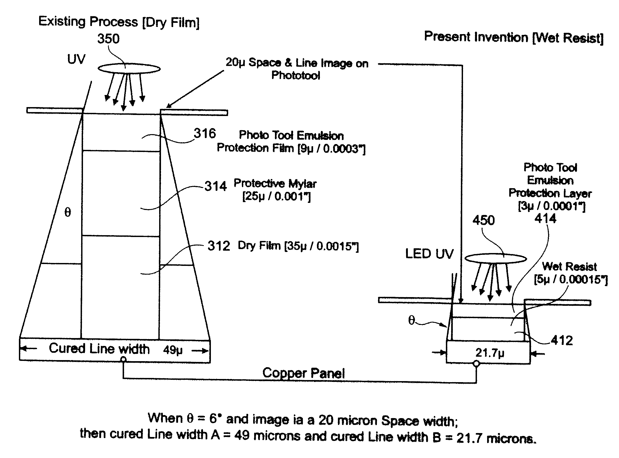
Although prior techniques exist in the art for producing thin lines suitable for forming PCBs, many of these techniques suffer from a number of significant disadvantages.
For example, many previous techniques suffer from poor resolution.
Moreover, techniques which do provide high resolution usually require complex apparatus such as sophisticated laser equipment.
A further problem is that previous techniques have required the use of partially cured dry films of photopolymer which are usually supp

Method used


Image

  • Photoimaging Method and Apparatus
  • Photoimaging Method and Apparatus
  • Photoimaging Method and Apparatus

Examples


Example

[0095]In one embodiment, the invention described herein relates to a substrate that includes:

[0096]a substrate with a cladding, and

[0097]a layer comprising (i) a pattern of electrically-conductive circuitry comprising wires overlying the cladding, wherein the thickness of the wires is about 0.1-5 μm, and (ii) a polymeric film coating on at least part of the cladding, and residing between the wires.

[0098]In another embodiment, the invention described herein relates to a substrate that includes

[0099]a substrate with a cladding, and

[0100]a layer comprising (i) a pattern of electrically-conductive circuitry comprising wires overlying the cladding, and (ii) a polymeric film coating on at least part of the cladding, and residing between the wires, wherein the substrate is made from a plastics sheet.

[0101]The wires can be prepared from metals such as silver, gold and / or copper, or, alternatively or additionally, conducting polymers such as PEDOT.PSS (Poly(3,4-ethylenedioxythiophene) poly(s...


PUM

PropertyMeasurementUnit
Lengthaaaaaaaaaa
Thicknessaaaaaaaaaa
Lengthaaaaaaaaaa

Abstract

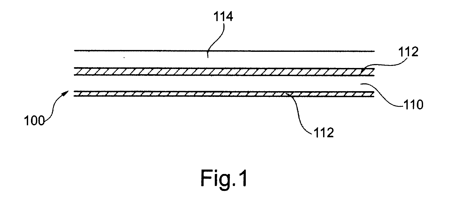
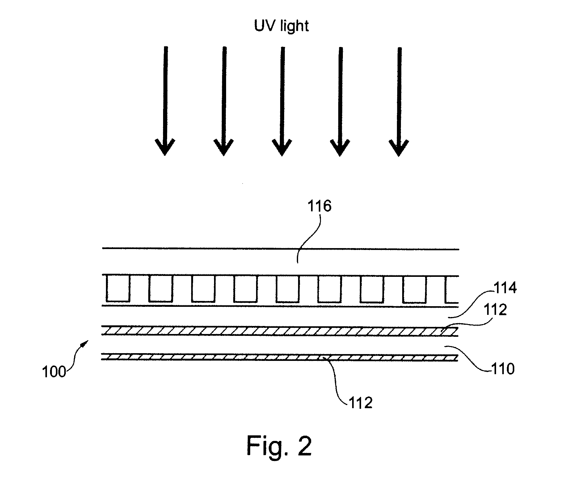
There is herein described a method and apparatus for photoimaging. In particular, there is described a method and apparatus for photoimaging a substrate covered with a wet curable photopolymer, wherein the photoimaged substrate is used to form images such as electrical circuits.

Description

CROSS REFERENCE TO RELATED APPLICATIONS[0001]This is a continuation-in-part of U.S. patent application Ser. No. 12 / 499,671, filed on Jul. 8, 2009, which in turn is a continuation-in-part of U.S. patent application Ser. No. 12 / 212,742 filed Sep. 18, 2008, which itself claims priority of United Kingdom Patent Application No. 0813196.3, filed Jul. 18, 2008. U.S. patent application Ser. No. 12 / 499,671 also claims priority under 35 U.S.C. §119 of United Kingdom Patent Application No. 0813196.3, filed Jul. 18, 2008 and under 35 U.S.C. §120 of U.S. Provisional Patent Application No. 61 / 149,200 filed Feb. 2, 2009. The disclosures of all of the foregoing applications are hereby incorporated herein by reference in their respective entireties, for all purposes.FIELD OF THE INVENTION[0002]The present invention relates to a method and apparatus for photoimaging. More particularly, the present invention relates to a method and apparatus for photoimaging a substrate covered with a wet curable phot...

Claims


Application Information

Patent Timeline
IPC IPC(8): H05K3/12H05K1/09H05K1/03
CPCH05K2203/0793H05K2203/1572H05K3/12H05K1/0306H05K1/09G03F7/2014G03F7/2032H05K1/0393H05K3/0082H05K3/064H05K2203/0278H05K2203/056H05K2203/0759H05K2203/1545G03F7/2012
Inventor KENNETT, CHARLES JONATHANHAMILTON, SHEILA
Owner RAINBOW TECH SYST
Why Eureka
Try Eureka