Surface light source device

a light source and surface technology, applied in the direction of lighting and heating apparatus, planar/plate-like light guides, instruments, etc., can solve the problem of insufficient effect to suppress luminance variation, increase and decrease of the maximum inclined angle of the light exit pattern b>17/b>, and increase and decrease of the degree of light scattering.

Active Publication Date: 2013-09-19
TOHOKU DENSHI CO LTD
View PDF5 Cites 12 Cited by
  • Summary
  • Abstract
  • Description
  • Claims
  • Application Information

AI Technical Summary

Benefits of technology

[0009]The present invention has been made in view of the above technical problems, and an object of at least one embodiment thereof is to provide a surface light source device that can reduce variation in luminance near a light source without decreasing intensity of a light exit pattern in the surface light source device in which the light exit pattern that outputs light through a light exit surface is formed in a light guide plate.

Problems solved by technology

Accordingly, there is a practical problem in both the cases where the maximum inclined angle of the light exit pattern 17 is increased and decreased.
When the maximum inclined angle of the light exit pattern reaches the minimum value within the distance from the light exit pattern located closest to the light incident surface, the degree of light scattering is insufficient, and the effect to suppress the variation in luminance is insufficiently obtained in the region near the light incident surface.

Method used


Image

  • Surface light source device
  • Surface light source device
  • Surface light source device

Examples


first embodiment

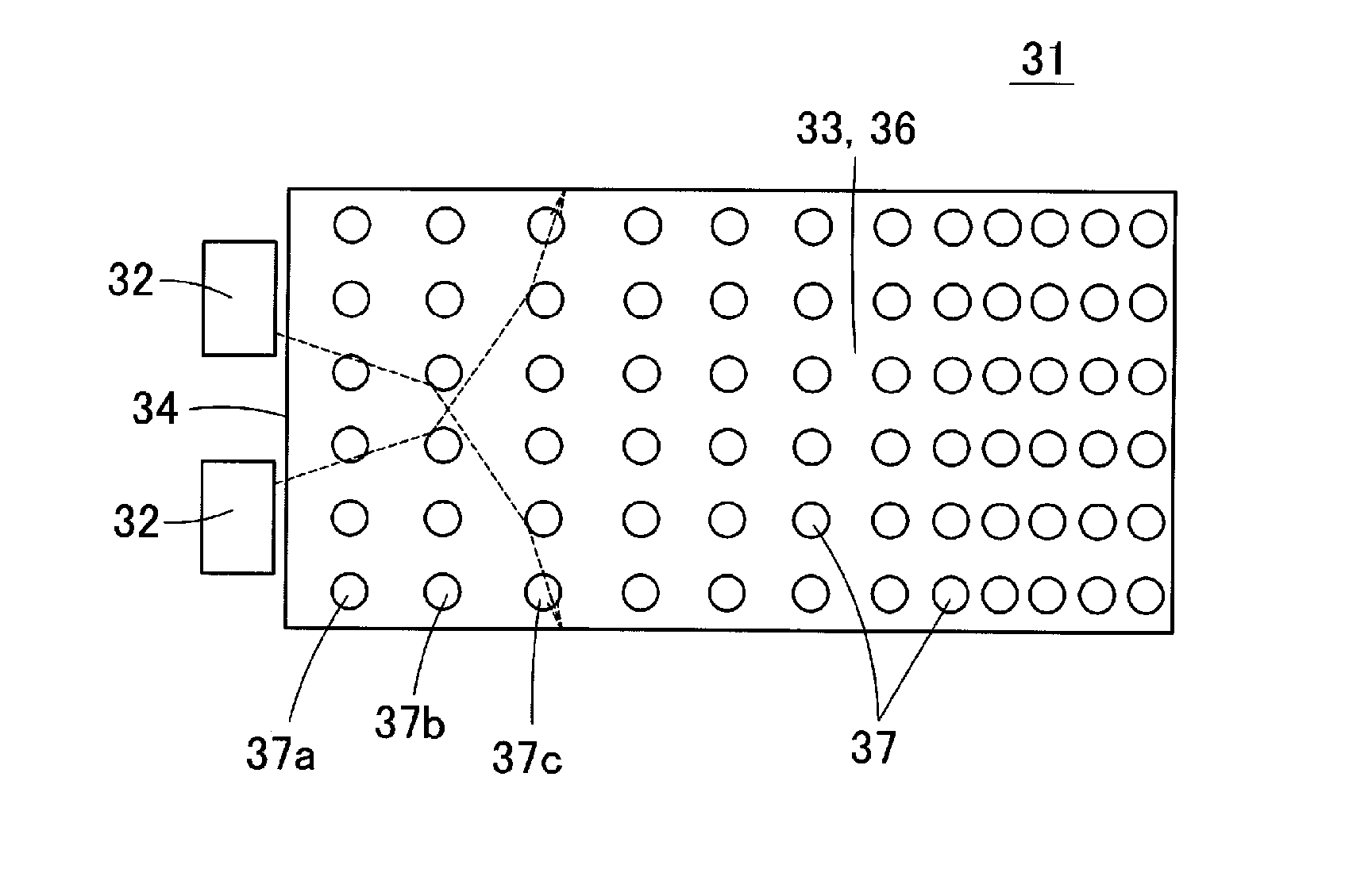
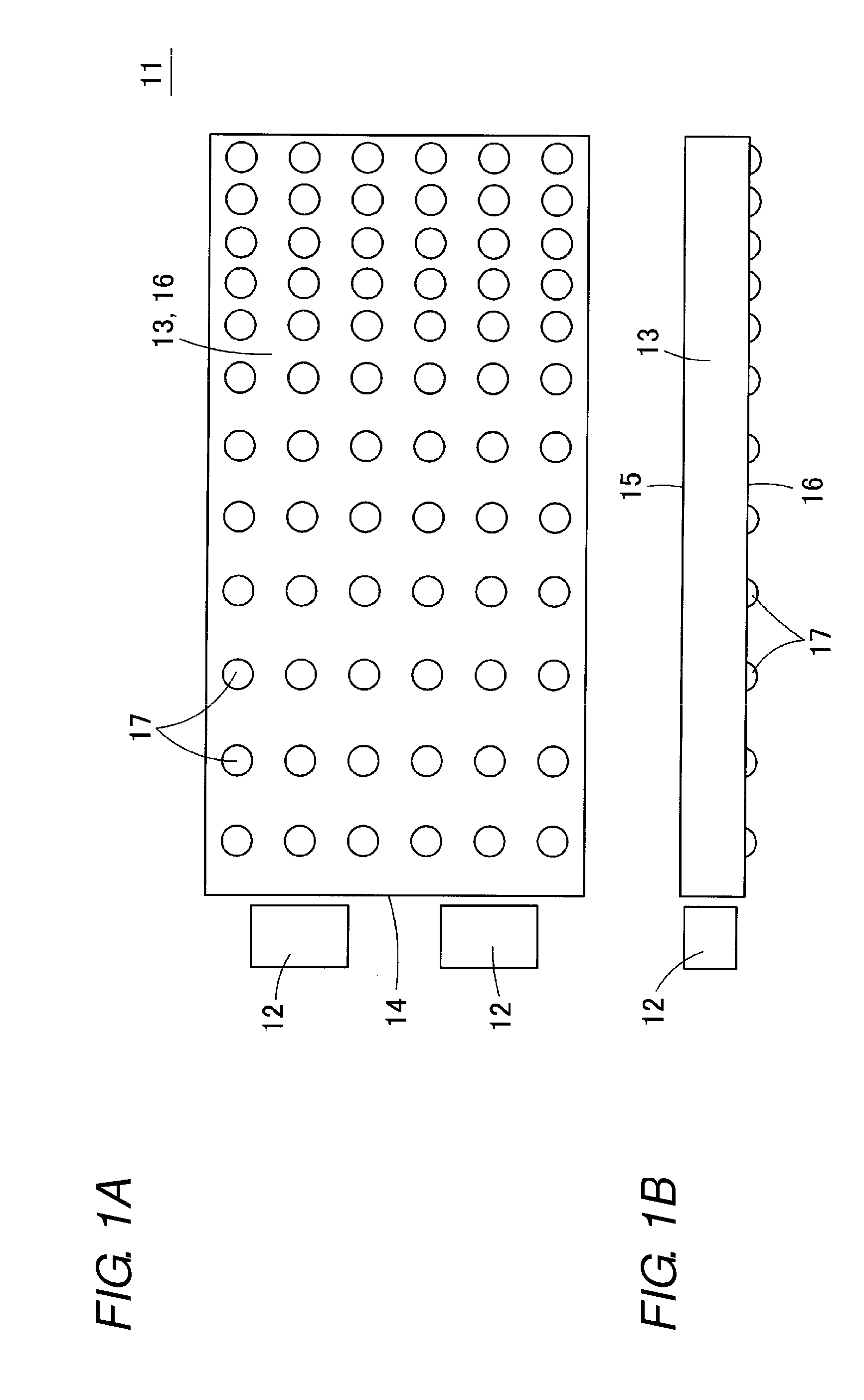
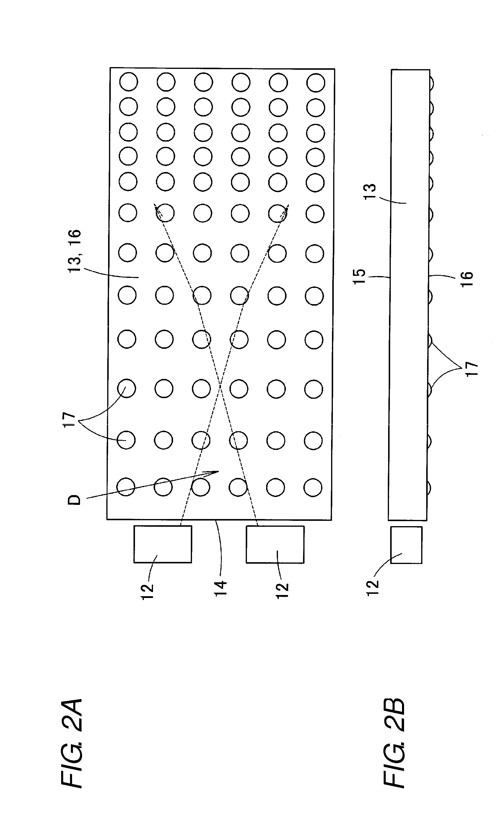
[0041]A surface light source device 31 according to a first embodiment of the present invention will be described below. FIG. 4A is a schematic plan view of the surface light source device 31 of the first embodiment, and FIG. 4B is a schematic bottom view of the surface light source device 31.

[0042]The surface light source device 31 includes a light source 32 and a light guide plate 33. The light source 32 incorporates therein one or a plurality of LEDs (chips). In the light source 32, the LED emits light to output white light from a light exit window (an emission surface) of a front surface.

[0043]In the light guide plate 33, an upper surface and a lower surface are formed into plate shapes parallel to each other. The light guide plate 33 is integrally formed using high-refractive-index transparent resins, such as an acrylic resin, a polycarbonate resin (PC), a cycloolefin-based material, and polymethylmethacrylate (PMMA). The upper surface of the light guide plate 33 constitutes a ...

second embodiment

[0055]FIG. 10A is a schematic plan view illustrating a surface light source device 41 according to a second embodiment of the present invention. FIG. 10B is a schematic bottom view illustrating the surface light source device 41. FIG. 10C is a schematic side view illustrating the surface light source device 41. In the surface light source device 41 of the second embodiment, a coarse surface 42 having arithmetic average roughness (Ra) of 0.1 μm or less is used as the light exit surface 35. Because other configurations are identical to those of the surface light source device 31 of the first embodiment, the description is omitted by citing the reference numeral identical to that of the first embodiment (the same applies to other embodiments).

[0056]In the second embodiment, since the coarse surface 42 is used as the light exit surface 35, the light output from the light exit surface 35 can be scattered to widen the directional pattern. The reason for the restriction to the arithmetic a...

third embodiment

[0057]FIG. 11A is a schematic plan view illustrating a surface light source device 46 according to a third embodiment of the present invention. FIG. 11B is a schematic bottom view illustrating the surface light source device 46. FIG. 11C is a schematic side view illustrating the surface light source device 46. FIG. 11D is a schematic end view illustrating the surface light source device 46.

[0058]In the surface light source device 46 of the third embodiment, a lenticular lens 47 is formed on the light exit surface 35 of the light guide plate 33. In the lenticular lens 47, a lens surface extends in a direction perpendicular to the light incident surface 34, and the lens surface is arranged in a width direction. The directional pattern of the light output from the light exit surface 35 can be widened in the width direction of the light guide plate 33 by providing the lenticular lens 47.


PUM


Abstract

A variation in luminance is reduced near a light source without decreasing intensity of a light exit pattern. A light source is disposed and a light exit pattern is formed. The light exit pattern reflects light guided in a light guide plate and outputs the light. In inclined angles of tangents of the light exit patterns in a section passing through a center axis of the light exit pattern, a largest inclined angle of the tangent is defined as a maximum inclined angle of the light exit pattern. At this time, in the light exit pattern provided in the light guide plate, the maximum inclined angle is decreased with increasing distance from a light incident surface in a region near the light incident surface, and the maximum inclined angle is decreased or kept constant with increasing distance from the light incident surface in a region distant from the region near the light incident surface.

Description

[0001]Priority is claimed under 35 U.S.C. §119 to Japanese Patent Application No. JP2012-058722 filed on Mar. 15, 2012, which is hereby incorporated by reference in its entirety.BACKGROUND[0002]1. Technical Field[0003]The present invention relates to a surface light source device, and specifically to a surface light source device that is used as a backlight of a liquid crystal display.[0004]2. Related Art[0005]FIG. 1A is a view illustrating a surface light source device of a conventional example when the surface light source device is viewed from a lower surface side. FIG. 1B is a side view illustrating the surface light source device of the conventional example. In a surface light source device 11, a plurality of light sources 12 are disposed while facing a light incident surface 14 of a light guide plate 13. The light guide plate 13 is formed into a flat-plate shape using a high-refractive-index transparent resin, and a plurality of spherical light exit patterns 17 are projected o...

Claims


Application Information

Patent Timeline
Patent Type & Authority Applications(United States)
IPC IPC(8): F21V8/00
CPCG02B6/002G02B6/0061G02B6/0035G02B6/0036
Inventor KURATA, GOUOTAKEMURA, KOICHIHIROTA, KAZUHIDEKISHIMOTO, JUNSHINOHARA, MASAYUKI
Owner TOHOKU DENSHI CO LTD
Why Eureka
Try Eureka