Toner density sensor and image forming apparatus

a toner density sensor and image forming technology, applied in the field of toner density sensors, can solve the problems of affecting the position of the mounted elements, and achieve the effects of reducing the size of the toner density sensor, narrowing the light path, and suppressing the variation in detection accuracy

Active Publication Date: 2013-09-19
ORMON CORP
View PDF2 Cites 8 Cited by
  • Summary
  • Abstract
  • Description
  • Claims
  • Application Information

AI Technical Summary

Benefits of technology

[0013]Thereat, it is a main object of the present invention to make a balance between suppression of variations in detection accuracy and realization of size reduction.
[0015]In this configuration, light applied from the light emitting part passes through the irradiation path, to be reflected at the detection target, and then passes through the light receiving path, to be received at the light receiving part. In traveling of this light, when the diaphragm unit is formed at the irradiation path, the diaphragm unit narrows light applied from the light emitting part to a desired irradiated range and suppress irradiation of a range other than the desired range with light regardless of a position of the light emitting part. On the other hand, when a diaphragm unit is formed at the light receiving path, the diaphragm unit allows the light receiving part to receive light in a predetermined detected range in the reflected light, and suppresses entering of light from a range other than the desired range. In such a manner, the diaphragm unit suppresses variations in detection accuracy.
[0016]This diaphragm unit is separated into two portions, and also disposed on the upper case provided on the front surface of the substrate and on the lower case provided on the rear surface of the substrate. That is, the diaphragm unit lower portion constituting the lower side portion of the diaphragm unit is arranged in the lower case provided on the rear surface of the substrate, and protrudes from the rear surface to the front surface of the substrate through the through hole, and molding is thus possible even when a required amount of protrusion from the front surface of the substrate is extremely small.
[0018]According to the present invention, with the configuration as described above where the diaphragm unit lower portion constituting the lower-side portion of the useful diaphragm unit is provided in the lower case and protruded from the rear surface to the front surface of the substrate, it is possible to mold the diaphragm unit lower portion even when a required amount of protrusion from the front surface of the substrate is extremely small. For this reason, even when the light emitting part and the light receiving part are reduced in size and a center position of the diaphragm unit gets closer to the front surface of the substrate, it is possible to reliably obtain the diaphragm unit that narrow the light path.
[0019]It is therefore possible to suppress variations in detection accuracy due to provision of the diaphragm unit, and further to realize size reduction of the toner density sensor by means of size reduction of the light emitting part and the light receiving part.

Problems solved by technology

However, since the elements as the light emitting part 102 and the light receiving parts 103, 104 are surface-mounted on the substrate 105 as described above, there has been a problem in that mounted positions of the elements may be displaced.

Method used


Image

  • Toner density sensor and image forming apparatus
  • Toner density sensor and image forming apparatus
  • Toner density sensor and image forming apparatus

Examples


Embodiment Construction

[0029]Hereinafter, preferred embodiments of the present invention will be described with reference to the drawings.

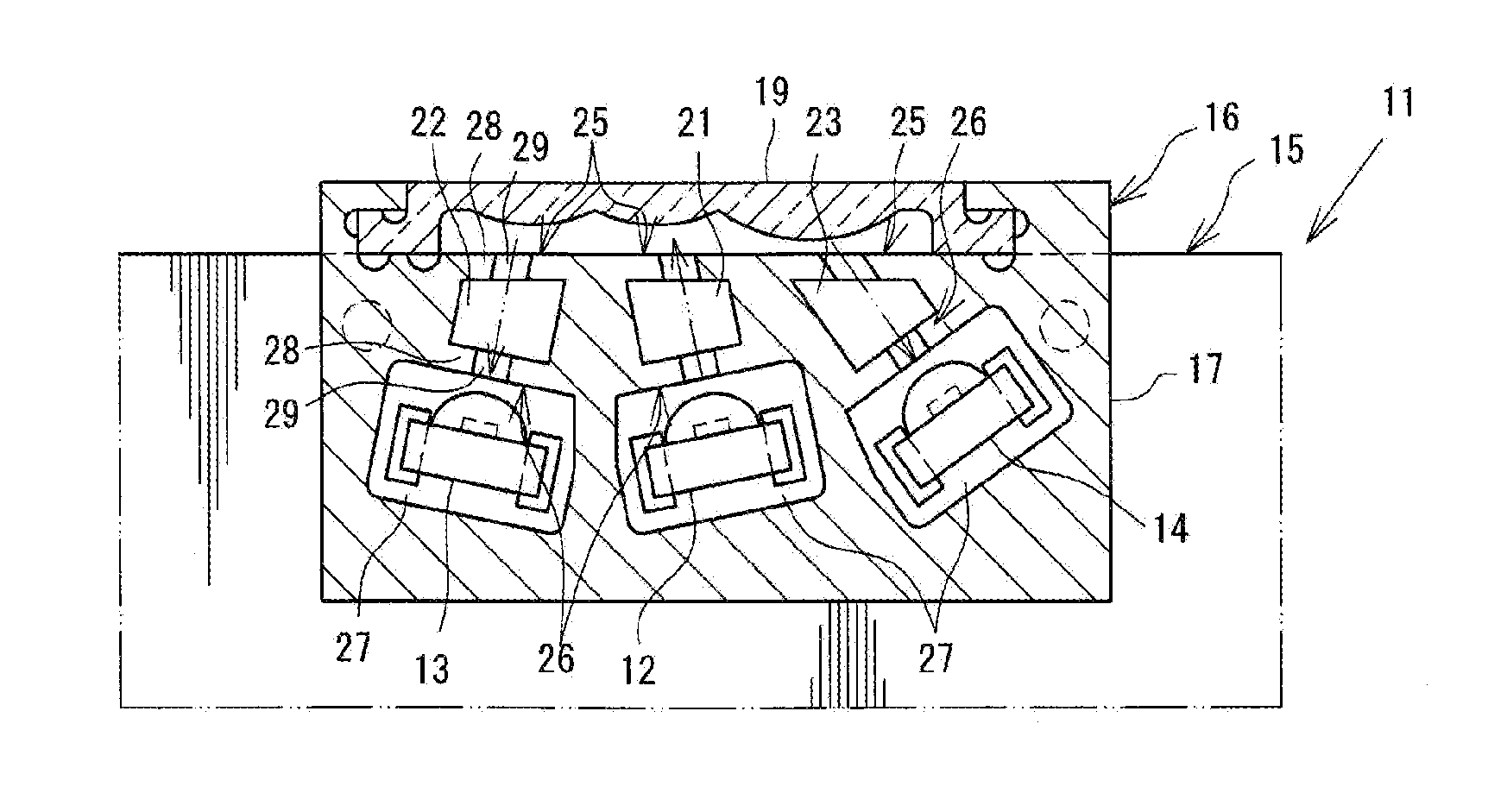
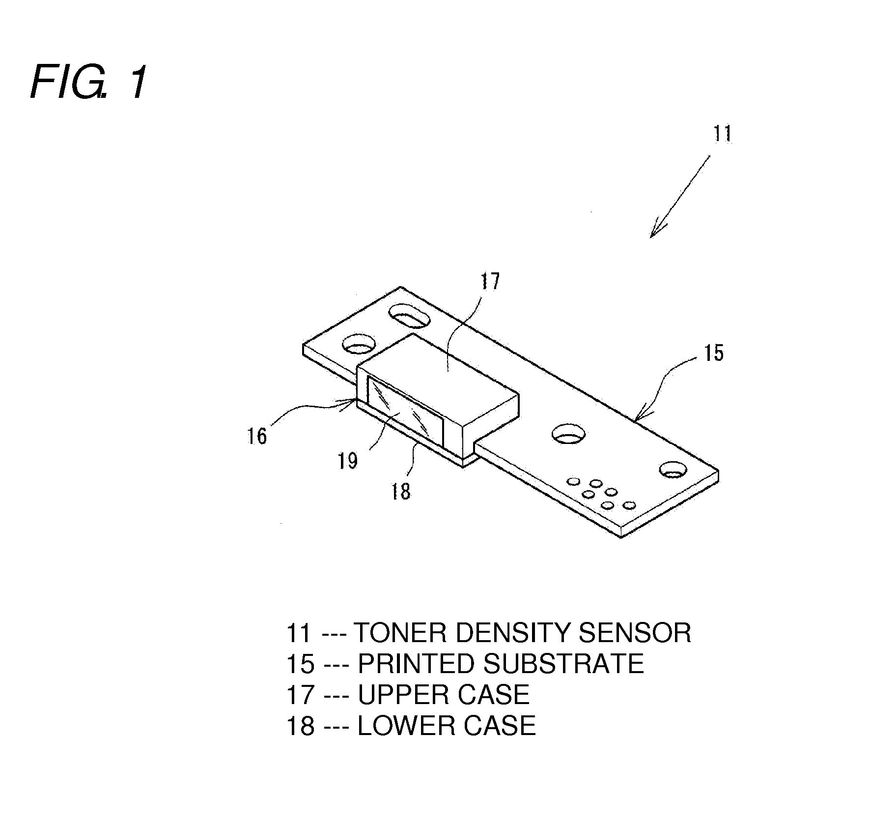
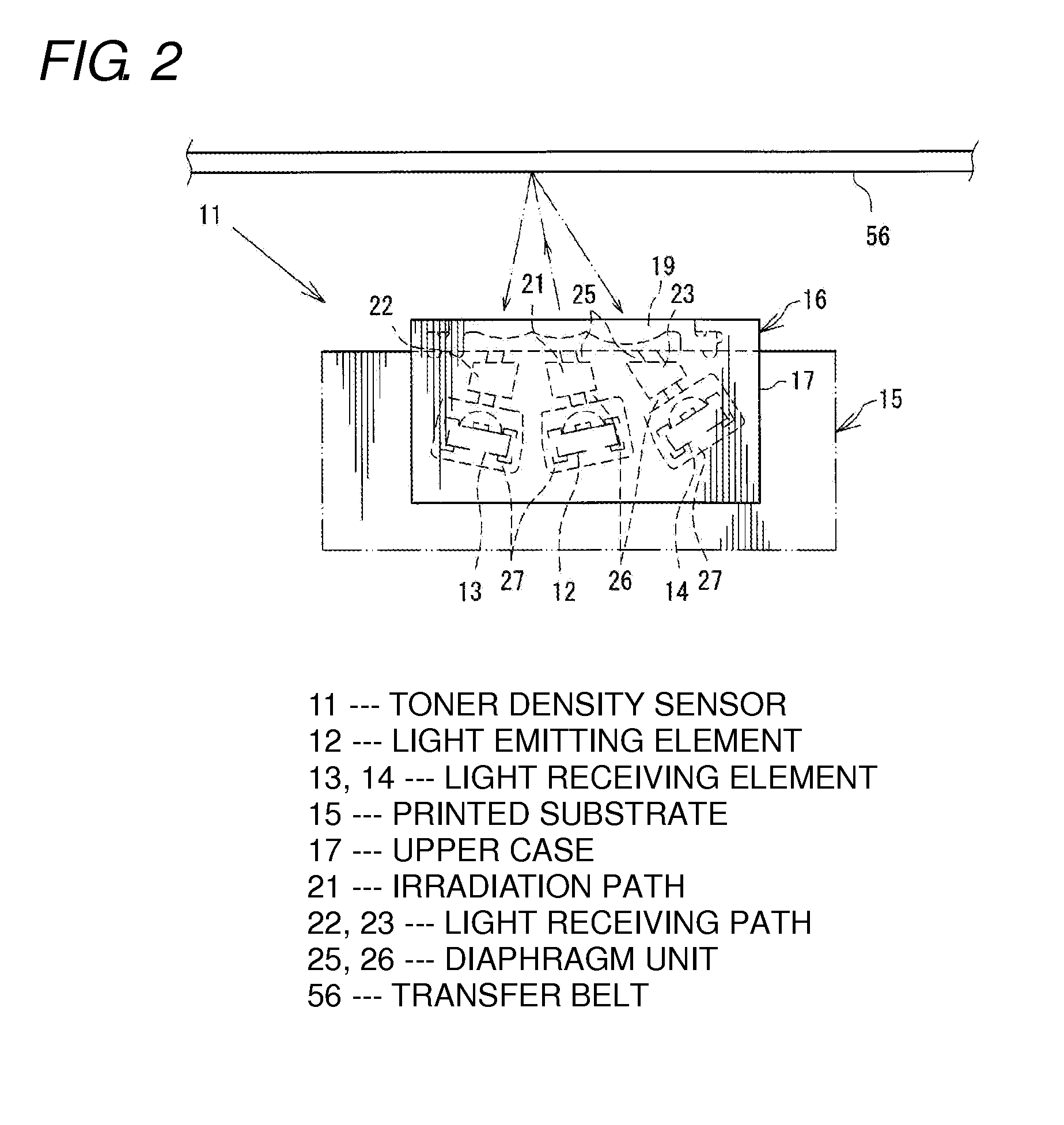
[0030]FIG. 1 is a perspective view of a toner density sensor 11, and FIG. 2 is a front view schematically explaining the toner density sensor 11.

[0031]The toner density sensor 11 is mounted in an image forming apparatus 51 as shown in FIG. 3. The image forming apparatus 51 is, for example, a color laser printer or the like.

[0032]First, a schematic structure of the image forming apparatus 51 will be described as follows.

[0033]The image forming apparatus 51 is configured such that an original reading unit 52 is provided in an upper portion, an image is formed in an image forming unit 53 based on original data read with the original reading unit 52, the image is transferred to a paper sheet 54a fed from a sheet feeding unit 54 arranged at lower part, and the paper sheet is discharged from the sheet discharge unit 55 at upper part.

[0034]The image formation in the image form...


PUM


Abstract

A toner density sensor comprising: a light emitting element that emits light; a light receiving element that receives reflected light emitted from the light emitting part and reflected at a detection target; a light path for passage of emitted and reflected light formed along the front surface of a printed substrate on which the light emitting element and the light receiving element are surface-mounted; and a diaphragm unit that is formed at and partially narrows this light path, wherein the diaphragm unit is divided into two portions, a diaphragm unit upper-portion and a diaphragm unit lower-portion, and these are disposed in an upper case covering the front surface of the printed substrate and in a lower case covering the rear surface of the printed substrate. In the printed substrate, a through hole is formed for protrusion of the diaphragm unit lower portion from the rear surface to the front surface.

Description

TECHNICAL FIELD[0001]The present invention relates to a toner density sensor that is used for an image forming apparatus such as a copying machine, a printer, and a facsimile machine, and particularly relates to such a toner density sensor as to make a balance between suppression of variations in detection accuracy and realization of size reduction.RELATED ART[0002]A toner density sensor is an important component for obtaining optimum image quality in an image forming apparatus. As shown in FIG. 8, a toner density sensor 101 includes a light emitting part 102 that applies light, light receiving parts 103, 104 that receive light having been applied from the light emitting part 102 and reflected at a detection target, and an amplification unit that amplifies detection voltages of the light receiving parts 103, 104. When an image forming apparatus mounted with the toner density sensor 101 is an intermediate transfer type apparatus where a toner image primarily transferred to an interme...

Claims


Application Information

Patent Timeline
Patent Type & Authority Applications(United States)
IPC IPC(8): G03G15/00
CPCG03G15/5025G03G15/0862G03G15/0855G03G15/5041G03G15/5058G03G15/5054G01J1/02G01N21/47G03G15/00
Inventor TAISHI, YOSHITAKAKAWAI, HAJIME
Owner ORMON CORP
Why Eureka
Try Eureka