Retention mechanism device

a technology of a retention mechanism and a spring arm, which is applied in the direction of coupling device details, coupling device connection, coupling/disengagement of coupling parts, etc., can solve the problems of electrical contacts not fully engaged, electrical plugs can be partially removed, electrical contacts can be inadvertently misaligned, etc., to reduce the stress in the spring arm and reduce the stress in the arm. , the effect of easy assembly

Inactive Publication Date: 2013-09-19
APPLE INC
View PDF5 Cites 35 Cited by
  • Summary
  • Abstract
  • Description
  • Claims
  • Application Information

AI Technical Summary

Benefits of technology

[0006]In view of the shortcomings in currently available electronic connectors described above, embodiments of the invention relate to improved connectors that allow for improved retention forces between an electrical tab and a connector receptacle, an increased normal force between the electrical contacts of the electrical tab and the receptacle, improved ease of use by providing a more consistent feel when a tab is inserted and extracted from its corresponding receptacle, and an increased life span of the device over many cycles of use. Although many aspects and features of the invention are described in relation to the electrical connectors depicted in the accompanying figures, it is appreciated that these features and aspects can be used in a variety of different applications and connector device. Many other commonly used data connectors include standard USB and mini USB connectors, FireWire connectors, as well as many of the proprietary connectors used with common portable electronics.
[0017]Another example method for retaining a connector plug within a receptacle in an electrical connector assembly includes: inserting a connector plug into the receptacle so as to contact an inward facing surface of each of a pair of spring arm retention features disposed within the receptacle; advancing the connector plug so as to displace each resilient arm laterally outward from an insertion axis along which the connector plug is inserted; contacting an outward facing surface of each arm with a corresponding lubricating member disposed within the receptacle so as to release a lubricant from the lubricating member onto a surface of each resilient arm, and; mating the connector plug within the receptacle by advancing the connector plug until the spring arm retention features are slidably received within corresponding recessed retaining features of the connector tab, wherein the lubricant facilitates sliding of the interfacing surfaces of the retention features. The methods may further include contacting the lubricating member with the displaced resilient arm so as to reduce the stress within the arms during insertion.

Problems solved by technology

In many conventional connector designs, the normal force is limited by the tightness of the fit, which often degrades over time as the connector is subjected to many cycles of use.
Despite such designs, in many connector devices, the electrical plug can inadvertently become misaligned, partially withdrawn, or removed from the receptacle entirely.
Additionally, many conventional designs provide little or no indication as to when the plug connector is properly positioned within the receptacle so that a user may unknowingly insert the plug connector in such a manner that the electrical contacts are not fully engaged and do not properly function.
After many cycles of use, however, the lubrication may be worn away such that the connector returns to a non-lubricated state.
The increased friction or wear and tear on interfacing surfaces in a non-lubricated state may degrade the ability to easily insert and remove the connector plug from the receptacle as well as the integrity of the connection when electrically coupled.

Method used


Image

  • Retention mechanism device
  • Retention mechanism device
  • Retention mechanism device

Examples


Embodiment Construction

[0039]The present invention will now be described in detail with reference to certain embodiments thereof as illustrated in the accompanying drawings. In the following description, numerous specific details are set forth in order to provide a thorough understanding of the present invention. It will be apparent, however, to one skilled in the art, that the present invention may be practiced without some or all of these specific details. In other instances, well known details have not been described in detail in order not to unnecessarily obscure the present invention.

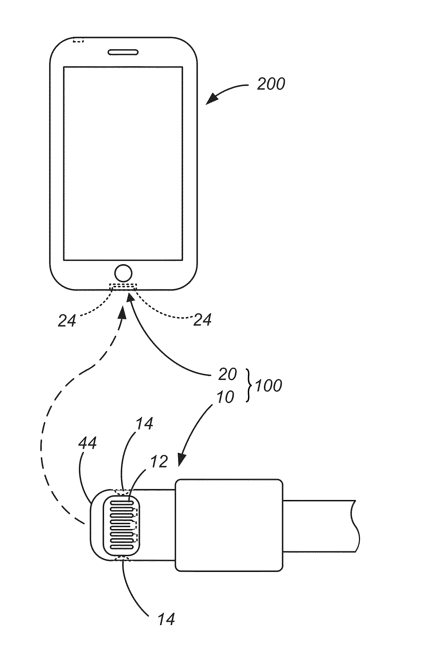
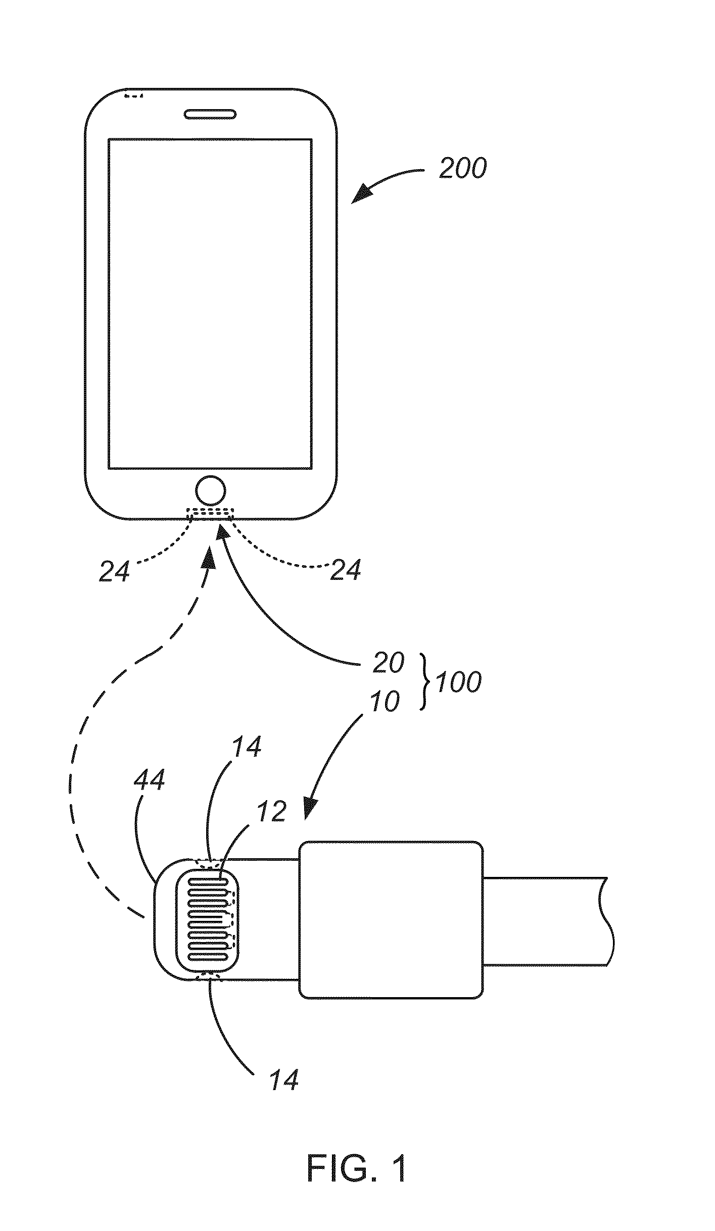
[0040]In order to better appreciate and understand the present invention, reference is first made to FIG. 1 which is a simplified schematic representation of connector device 100 having a retention latch mechanism according to an embodiment of the invention. It is worth noting that the components in FIG. 1 are not drawn to scale. As shown in FIG. 1, connector device 100 includes a plug connector 10 compatible with a corr...


PUM

PropertyMeasurementUnit
angleaaaaaaaaaa
thickaaaaaaaaaa
thickaaaaaaaaaa

Abstract

A retention latch mechanism having corresponding retention features and stress reducing members is provided herein. In an exemplary embodiment, the retention latch mechanism comprises a pair of spring arm retention features of a receptacle engageable with a corresponding pair of recessed retention features of an insertable tab and one or more backup spring members for reducing stress within the spring arms during insertion of the tab into the receptacle. The backup spring may be positioned adjacent an outward facing surface such that outward lateral deflection of the spring arms deflects the backup spring thereby reducing force within the spring arm. The backup spring may include any or all of a bent portion of an associated bracket or arm member, a wire, a loop, a complementary spring arm, dual backup springs, elastomeric members and self-lubricating members. Methods of providing retention of a tab within a receptacle are also provided herein.

Description

CROSS-REFERENCES TO RELATED APPLICATIONS[0001]The present application is a non-provisional of, and claims the benefit of U.S. Provisional Patent Application No. 61 / 597,705, filed Feb. 10, 2012; U.S. Provisional Patent Application No. 61 / 602,057, filed Feb. 22, 2012; and U.S. Provisional Patent Application No. 61 / 693,228, filed Aug. 24, 2012, each of which the entire contents are incorporated herein by reference.BACKGROUND OF THE INVENTION[0002]The present invention relates generally to retention mechanisms, and in particular retention mechanisms for use in electrical connectors.[0003]Many devices include electrical connectors to facilitate communication between devices and / or recharging of the device by electrically coupling the device to an external power source. In a typical electrical connector system an electrical connection can be made between a plug connector and a corresponding receptacle connector by inserting the plug connector into the corresponding receptacle connector. G...

Claims


Application Information

Patent Timeline
Patent Type & Authority Applications(United States)
IPC IPC(8): H01R13/62H01R43/26
CPCH01R43/26H01R13/627H01R13/6275Y10T29/49208H01R2201/06H01R13/62H01R24/62
Inventor WEBER, DOUGLAS J.MATSUYUKI, NAOTOSLOEY, JASON S.DO, TRENT K.
Owner APPLE INC
Why Eureka
Try Eureka