Systems and Methods for a Control Valve

a flow control and valve system technology, applied in process and machine control, separation processes, instruments, etc., can solve the problems of significant durability and operability problems, noise generation, limiting their utility, etc., and achieve the effect of increasing or decreasing the flow rate of fluid

Inactive Publication Date: 2013-09-26
THE AEROSPACE CORPORATION
View PDF12 Cites 21 Cited by
  • Summary
  • Abstract
  • Description
  • Claims
  • Application Information

AI Technical Summary

Benefits of technology

[0010]In another embodiment, a method for controlling fluid flow can be provided. The method can include generating a pressure drop in the fluid flow by viscous dissipation within a valve com...

Problems solved by technology

This physical mechanism, while effective in many applications, can result in significant durability and operability problems such as noise generation, vibration, and cavitation erosion in severe service applications where the requirement is to generate very large pressure drops or to discharge to pressures very close to the vapor pressure of the flowing fluid.
Th...

Method used


Image

  • Systems and Methods for a Control Valve
  • Systems and Methods for a Control Valve
  • Systems and Methods for a Control Valve

Examples


Embodiment Construction

[0029]Embodiments of the invention will now be described more fully hereinafter with reference to the accompanying drawings, in which embodiments of the invention are shown. This invention may, however, be embodied in many different forms and should not be construed as limited to the embodiments set forth herein; rather, these embodiments are provided so that this disclosure will be thorough and complete, and will fully convey the scope of the invention. Like numbers refer to like elements throughout.

[0030]As used herein, the term “viscous dissipation” can refer to the dissipation of energy within a boundary layer between a body and a fluid, or in a fluid medium.

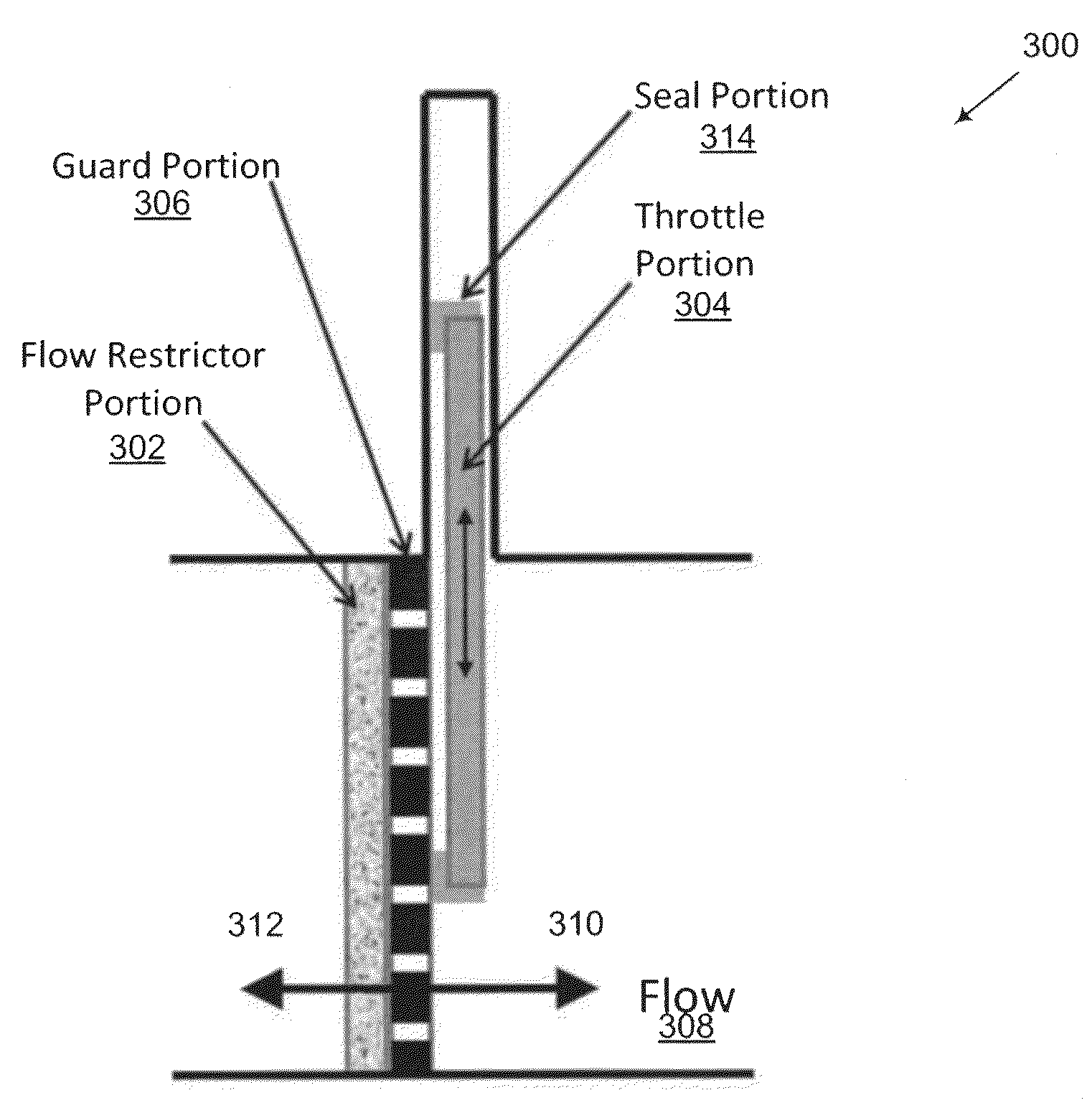
[0031]Certain embodiments of the invention generally provide for systems, methods, and apparatuses for a flow control valve. The valve design described herein with respect to embodiments of the invention can minimize or otherwise eliminate relatively high fluid velocities and associated problems found in conventional and exi...


PUM

PropertyMeasurementUnit
Flow rateaaaaaaaaaa
Viscosityaaaaaaaaaa
Pressure dropaaaaaaaaaa

Abstract

Embodiments of the invention relate to systems, methods, and apparatuses for a control valve. In one embodiment, a valve can be provided. The valve can include a flow restrictor portion operable to generate a pressure drop in a fluid flow by viscous dissipation; a throttle portion operable to change a flow rate of the fluid; and a guard portion operable to separate the flow restrictor portion from the throttle portion.

Description

TECHNICAL FIELD[0001]The invention relates generally to controlling flow, and more particularly to systems and methods for a flow control valve.BACKGROUND OF THE INVENTION[0002]Conventional flow control valves regulate flow using a variable area orifice that imposes a restriction on the fluid flow. An example conventional flow control valve is shown in FIG. 1. The pressure drop generated by this restriction is developed by accelerating the flowing fluid to high local velocities and then dissipating the resulting kinetic energy by means of turbulent dissipation. This physical mechanism, while effective in many applications, can result in significant durability and operability problems such as noise generation, vibration, and cavitation erosion in severe service applications where the requirement is to generate very large pressure drops or to discharge to pressures very close to the vapor pressure of the flowing fluid. An example graph illustrating the generated pressure drop along th...

Claims


Application Information

Patent Timeline
IPC IPC(8): F16K47/14G05D7/03
CPCG05D7/0635F16K47/14Y10T137/86035Y10T137/0318
Inventor EHRLICH, DANIEL A.
Owner THE AEROSPACE CORPORATION
Why Eureka
Try Eureka